ASCAT functional elements
The constituent elements of ASCAT are:
- Instrument Control Unit (ICU)
- Power Distribution Unit (PDU)
- Radio Frequency Unit (RFU)
- High Power Amplifier (HPA)
- Scatterometer Front End (SFE)
- Antenna Assemblies
- Hold-down and Release Mechanisms (HRM)
- Deployment Mechanisms (DM)
- Digital Processing Unit (DPU)
The following paragraphs briefly describe their function and some of their important design considerations.
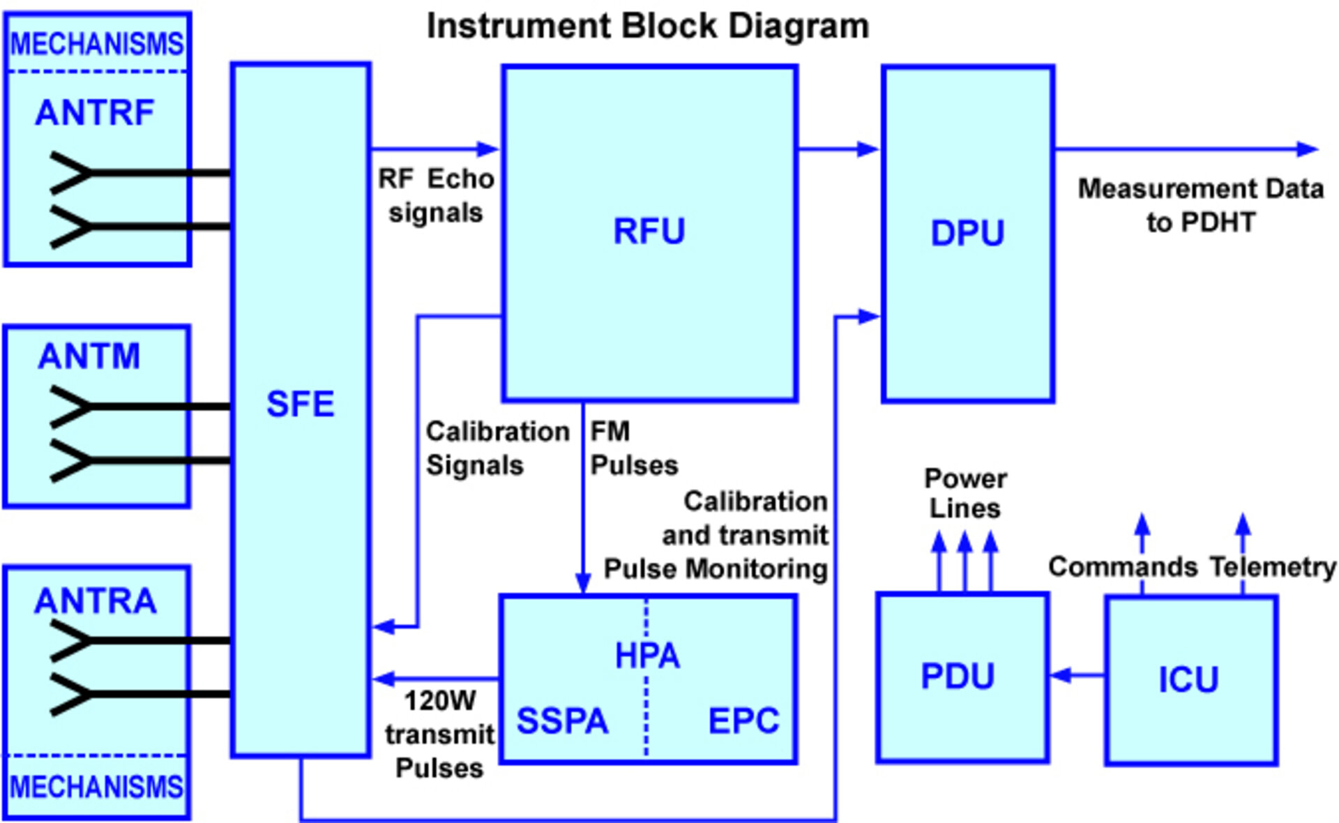
ASCAT is controlled by its Instrument Control Unit (ICU), which is responsible for:
- commanding the instrument
- supervising the status of its subsystems
- taking protective and recovery actions if necessary
- providing telemetry data
The ICU is able to power the various instrument subsystems by providing commands to the Power Distribution Unit (PDU). It is via the PDU that the redundancy configuration of the instrument can be selected.
Central to the operation of the instrument, the Radio Frequency Unit (RFU) is responsible for the generation of:
- low level frequency modulated pulses which form the basis of the transmit signals
- frequency modulated local oscillator signals which it uses in its internal mixer to down convert and de-chirp the received echoes
- calibration signals which track the transmitted power level and which are input to the receiver to determine the product of transmit power and receiver gain
- a clock signal for instrument timing
The RFU is a complex subsystem that relies on a thermally controlled crystal oscillator and a digital chirp generator to meet its design objectives. The chirp generator start frequency and chirp rate are numerically programmable and this allows different chirp characteristics to be selected for each of the antenna beams.
On the transmit side of the instrument, the low level transmit pulses generated by the RFU are input to the High Power Amplifier (HPA) where their peak power is boosted to 120 W peak for transmission to ground. The HPA consists of two elements:
- a multi-stage Solid State Power Amplifier (SSPA) which uses modern field effect transistor technology to generate the RF pulses
- an Electronic Power Conditioner (EPC), which provides the power supplies needed to run the SSPA
Transmit pulses from the HPA are routed to the Scatterometer Front End (SFE). The SFE is a complex microwave subsystem whose principal function is to provide a switching capability. This allows the transmit pulses to be directed to each of the six antennas in turn and allows echoes received by the relevant antenna to be directed into the receiver.
The SFE also provides:
- points at which the transmit power can be sampled and a calibration signal of similar level can be injected into the receive path
- low noise amplification of the received echoes
- a shutter to protect the low noise amplifier from RF leakage during pulse transmission which could otherwise lead to its destruction
The need for fast-acting switches giving a stable low-loss performance, has led to the selection of electronically operated latching waveguide circulators for this function. In order to produce compact units with redundant electronic functions and minimal electromagnetic compatibility problems, a unique Application Specific Integrated Circuit (ASIC) chip has had to be developed for the application.
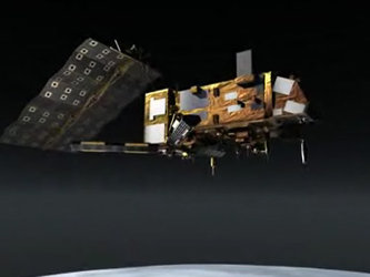
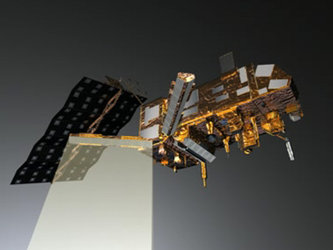
The three Antenna Assemblies that are connected to the SFE by waveguides are known by the names:
- ANTRF comprising the right-fore and left-aft antennas
- ANTM comprising the right- and left-mid antennas
- ANTRA comprising the right-aft and left-fore antenna
Except for the mid antenna assembly, which is fixed, the other two assemblies have associated Hold-down and Release Mechanisms (HRM) which hold the assemblies fixed during the launch phase and Deployment Mechanisms (DM) which transfer the assemblies from their stowed to operational positions after their release.
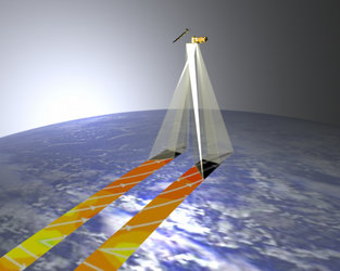
Like the designs used on the European Remote Sensing satellite (ERS) scatterometers, the ASCAT antennas are constructed from aluminium waveguides which radiate via slots cut longitudinally in the waveguide broad wall. The mid antennas each consist of three panels of eight waveguides and have an overall length of around 2.2 m, the side antennas each consist of four panels of six waveguides and have an overall length of 3 m. Segmentation of the antennas into panels is made to meet the requirements imposed by bandwidth and gain stability. Their radiating characteristics are selected to produce a shaped gain response in the range direction with minimal energy elsewhere and a low side lobe pattern in the across-range direction.
Echo signals received by the antennas are routed via the SFE to the RFU. Here they are de-chirped and down converted to baseband and are then passed to the Digital Processing Unit (DPU). In the DPU, each echo is sampled in time and this time series is manipulated to derive the echo spectrum. In order to reduce the down-link data rate, the DPU provides pre-processing (and hence compression) of the echo data. After supplementing this compressed data with calibration and various other housekeeping parameters, the data packets produced by the DPU are passed to the satellite payload data handling system for transmission to ground.