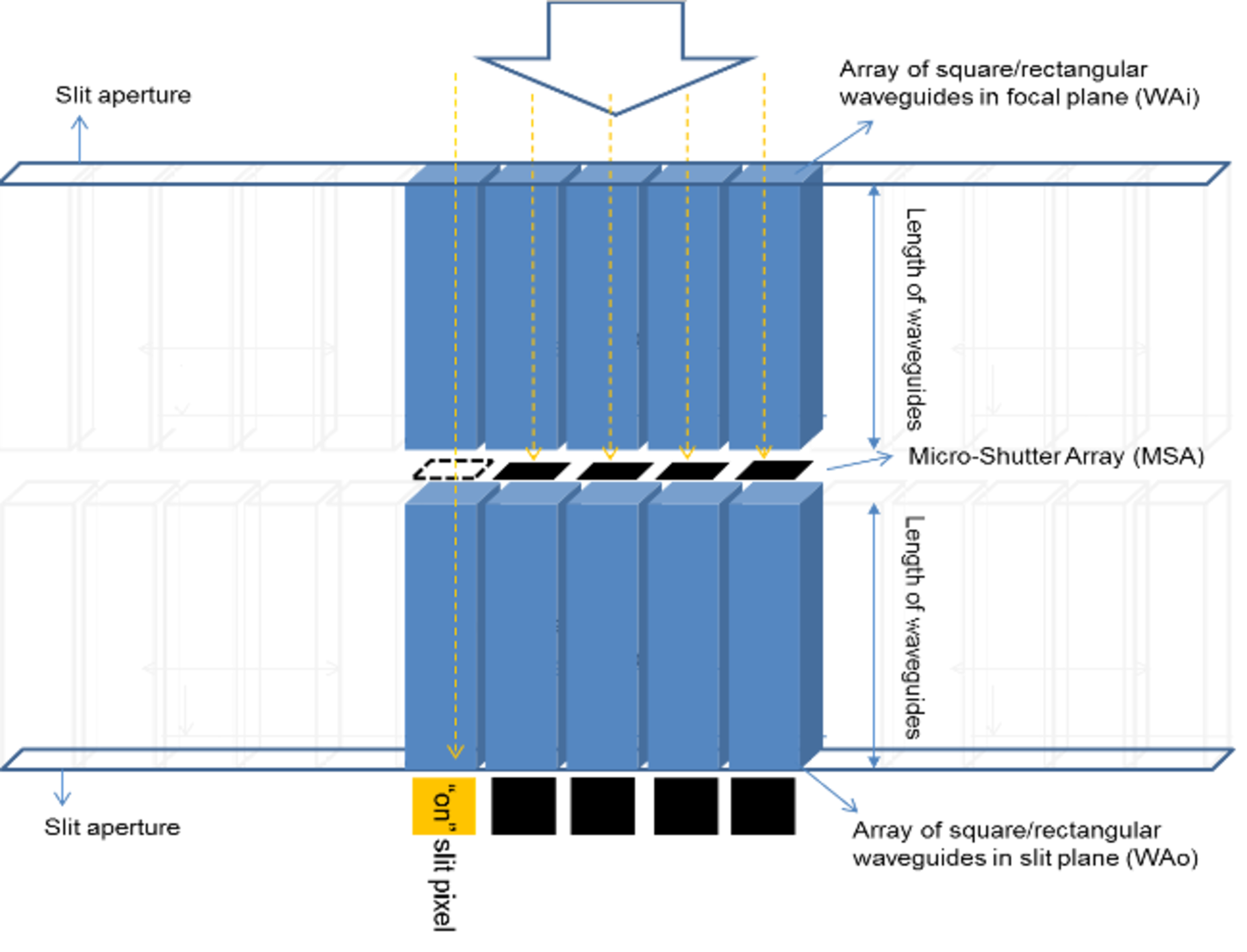
Figure 1: Schematic of a linear SSA
Figure 1: Schematic of a linear SSA. The SSA is placed in the focal plane of the front optics (e.g. telescope, objective) where the classical slit would be placed. The image field is coupled into the input waveguide array (WAi). On the other side, the spectrometer is fed by the output waveguide array (WAo). Between both waveguide arrays a Micro Shutter Array (MSA) unit is placed which modulates the light intensity of each of the waveguides of the WAi. To illustrate the basic functioning of the SSA, the pixel on the left is “on”, or transmits the light coupled into the waveguide as soon as the micro-shutter is open. On the other hand, all other SSA pixels are “off”, or not transmitting the light through the output waveguide, since they are blocked by the MSA. Such an SSA can be arranged also in a 2D-array. In this schematic the MSA is directly placed between both waveguide arrays, which corresponds to solution 1 discussed here.
.