SpaceFibre Port IP Core
A synthesizable VHDL implementation of a single-lane SpaceFibre port.
This IP was initially developed by Cobham Gaisler AB, Sweden, in the frame of ESA contract 4000116134/15/NL/LF.
Overview
SpaceFibre is a high-speed serial link mainly designed for payload data processing applications on board spacecraft. Like many other modern network architectures, SpaceFibre utilizes a Serialiser/Deserialiser (SerDes) circuit at its physical layer, allowing data rates of several Gigabits per Second.
Interfacing a SpaceFibre port from the user application is simple as it closely follows the procedure known from SpaceWire. A SpaceFibre port has one or more pairs of transmit and receive buffers, referred to as virtual channels, and each virtual channel behaves like a single SpaceWire interface, i.e. several SpaceWire network streams can be multiplexed onto one SpaceFibre link. The multiplexer is called medium access controller and is choosing the active virtual channel according to a number of Quality-of-Service (QoS) rules. Data is always transferred in frames with a size of 256 bytes or less. While such a data frame is passed to the physical link, it is also stored in an error recovery buffer. It remains in this buffer until the destination node acknowledges the correct reception of the frame, which is detected by checking a CRC checksum at the end of the frame. However, if the destination node sends a negative-acknowledgement (NACK) word instead, the frame is re-transmitted from the error-recovery buffer. Aside from data frames, SpaceFibre also supports broadcast frames, which are multi-purpose high-priority messages. These messages are comparable to SpaceWire time-codes but in addition to a simple sequence number they also comprise a data payload of 8 bytes. On the receive side, incoming data from the physical link is processed continuously, i.e. one 32-bit word is processed every clock cycle. To avoid buffer overruns in the virtual channel receive buffers, the communication between a virtual channel transmit buffer in the local node and the virtual channel receive buffer in the destination node is flow-controlled by means of Flow Control Token (FCT) words.
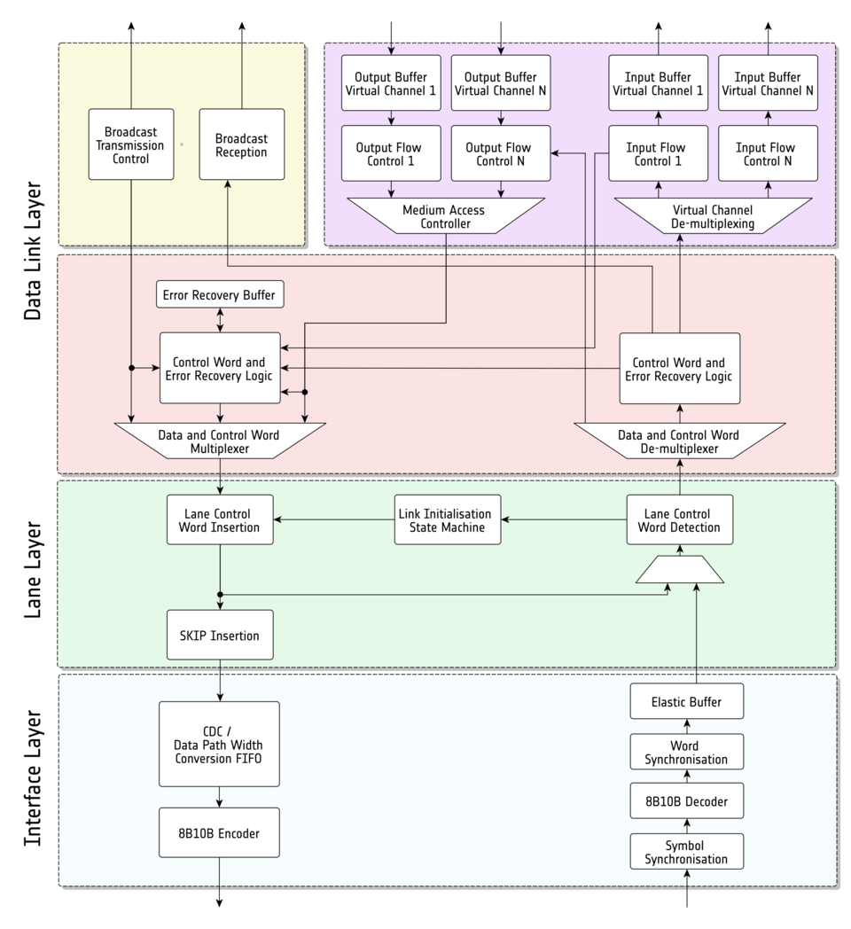
A simplified block diagram of the overall IP core architecture is depicted below. It comprises the following blocks:
- Data Link Layer: This layer is responsible for the handling of the user data via one or several virtual channel interfaces, which are flow-controlled and multiplexed onto the SpaceFibre link according to different QoS rules such as bandwidth allocation (purple). The data link layer also handles broadcasts, which are special messages with high priority - suitable for the exchange of e.g. time information or interrupts (yellow). Another important task of this layer is the creation and the exchange of control words and the handling of the error recovery logic (red).
- Lane Layer: This layer comprises the link initialization state machine needed to build up the link between the near-end and the far-end node (green).
- Interface Layer: This layer is an additional layer used for the adaptation of the SpaceFibre IP core to different SerDes. It includes on the receive side 8B/10B decoding, word synchronization and an elastic buffer and on the transmit side optional clock domain crossing logic and the 8B/10B encoding (blue).
Synthesis Estimates
Xilinx Virtex-5Q FX130T
- 4 Virtual Channels, VC buffer depth: 9, 32-bit SerDes interface, no internal 8B10B encoder/decoder
- Synthesis and Place & Route using Xilinx ISE 14.7
- Slice Registers: 2%, Slice LUTs: 4%, RAMs: 3%
- Expected achievable link data rate: 6.25 Gbps
Microsemi RT4G150
- 4 Virtual Channels, VC buffer depth: 9
- 20-bit SerDes interface, internal 8B10B encoder/decoder, additional CDC transmit buffer
- Synthesis and Place & Route using Libero SoC v11.7
- Flip-flops: 1.6%, LUTs: 3.8%, RAM64: 3.8%, RAM1K: 4.8%
- Expected achievable link data rate: 2.5 Gbps - 3.125 Gbps
Microsemi RTAX2000S
- 2 Virtual Channels, VC buffer depth: 9
- 16-bit SerDes interface, no internal 8B10B encoder/decoder, additional CDC transmit buffer
- Synthesis using Synplify Pro L-2016.03
- Combinational Cells: 27%, Sequential Cells: 19%, RAMs: 37%
- Expected achievable link data rate: 2 Gbps - 2.5 Gbps
Developer
Felix Siegle, Cobham Gaisler AB / European Space Agency, 2016 – 2019.
Current Release
Version 2.11, based on ECSS standard E-ST-50-11C-DIR1.
Special licensing restrictions
No special licensing conditions apply. For more information refer to the ESA IP-Cores licensing page.