Building the Soyuz launch facility at Europe’s Spaceport – part two
Transporter/erector system (continued)
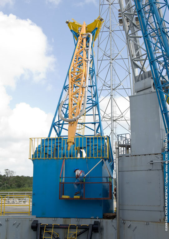
Personnel working on the coupler connection for the rail tug that will push the transporter/erector carrying the Soyuz launch vehicle from the launcher assembly and testing building (монтажно-испытательный корпус; montazhno-ispytatelniy korpus – MIK) to the launch pad. The transporter/erector will exit through doors at the far end of the building. On top of the transporter/erector is a large, yellow circular structure that supports the Soyuz when the launcher is rolled out in its horizontal position.
Transporter/erector test apparatus
Testing of the Soyuz transporter/erector will be carried out using this apparatus, which represents the dimensions of the lower part of the Soyuz launch vehicle. The two semi-circular panels in the foreground replicate the contact interface between two of the launcher’s lower strap-on boosters on the transporter/erector.
Railway infrastructure
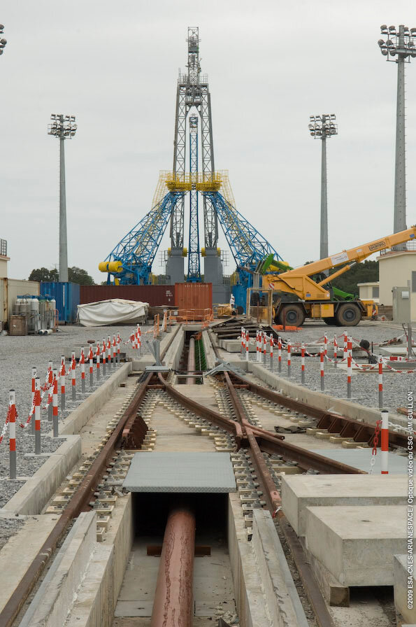
The railway infrastructure that supports Soyuz operations on the launch pad. In the foreground is a straight section of track that leads to the MIK, which will be used for the rollout of Soyuz launch vehicles on their transporter/erector. The curved portion of track (visible coming from the right) will be used for a railway tanker that brings kerosene propellant for fuelling of the four Soyuz boosters and Block A core stage. An additional load of kerosene that is maintained at a lower temperature will be delivered by truck for fueling of the Soyuz Block I third stage.
Soyuz primary support arms

The four primary support arms that suspend Soyuz over its launch pad, shown in the open position. During launcher checkout and final countdown, these arms are closed around the Soyuz, forming a support ring at the vehicle’s ‘waist.’ At liftoff, the upward movement of the launch vehicle decreases the load on the support arms, allowing them to swing outward under the influence of counterweights located at their base.
Close-up view of one of the four primary support arms, taken from inside the launch table. The upper, v-shaped portion serves as a segment of the support ring for Soyuz and also serves as a work platform to provide ground crews access to the launch vehicle.

The four main support arms for Soyuz, after their installation on the launch pad.
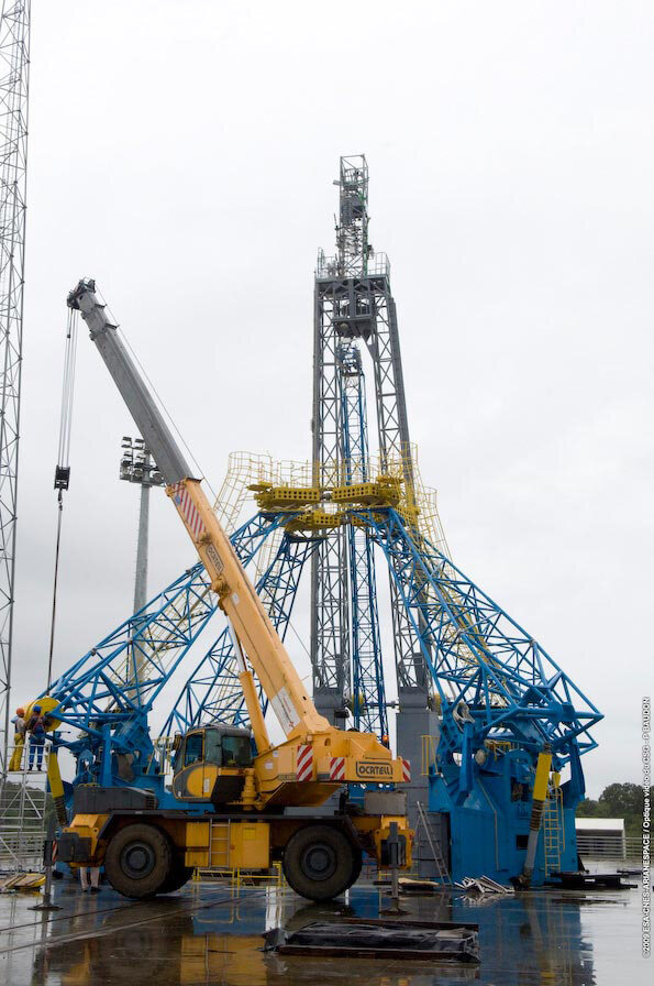
A crane installs counterweights at the base of one of the four Soyuz support arms. When this ingenious support arm concept was originally developed for the Soyuz launch vehicle family, its designers gave it the nickname ‘tulip’. This refers to the tilt-back movement of its four ‘petals’ – which begins when the arms are opened by the upward motion of the launch vehicle, followed by their tracking outward with the force provided by their counterweights.

Close-up view of the installation of the counterweights at the base of one of the support arms on the Soyuz launch pad.
return to part one of the article