Dutch company powering Galileo
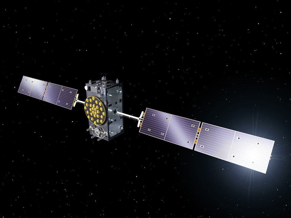
As they bathe the ground below them in test navigation messages, Europe’s Galileo satellites are kept alive by the Sun.
A pair of 5 m-long solar arrays supply 1.9 kilowatts of power – about the same as an average household’s consumption. These arrays are sourced from the Dutch Space company in the Netherlands.
Located just outside Leiden, a short drive from ESA’s Technical Centre, the Airbus Defence and Space subsidiary is based in what might appear to be a standard office building, the only clue to its space-based focus being an Ariane 5 frame outside.
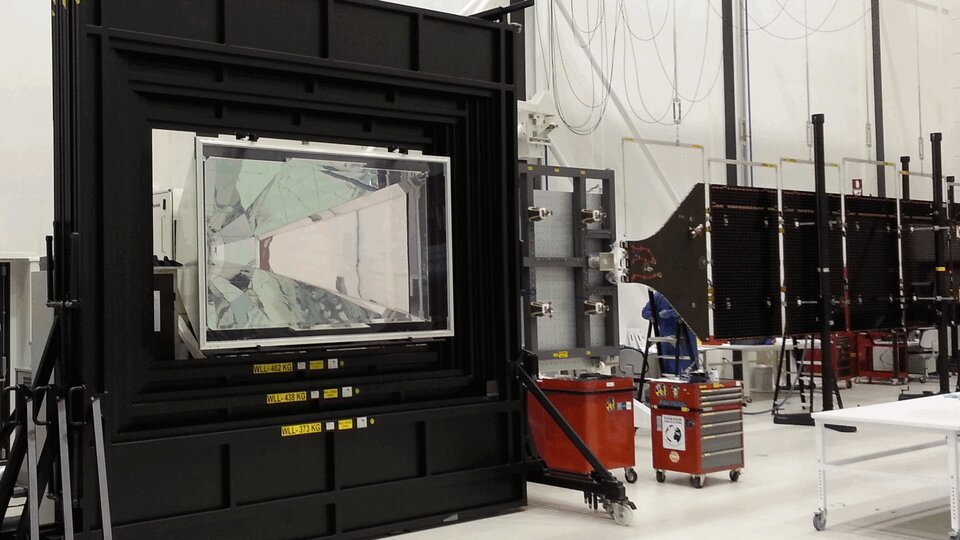
Inside its specialised facilities include a class 100 000 cleanroom, space simulation equipment and a ‘Very Large Sun Simulator’ – a giant camera flash able to test the electrical performance of the solar arrays the company supplies to about two thirds of ESA missions – which includes all Galileo satellites commissioned to date, as well as one of their two GIOVE predecessors.
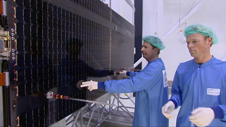
“Think of us as the prime contractor for Galileo’s solar panels,” explains senior project manager Jan Zuidam, overseeing the work for Dutch Space. “We build nothing directly ourselves, but – working with a network of partner companies – oversee the panels’ design, engineering management, assembly and testing, all performed here in these buildings.
The composite panel substrates, sourced from local Dutch company Airborne Composite, are equipped with solar cells in the Airbus Defence and Space facility in Ottobrunn, Germany, with the photovoltaic cells themselves sourced from German company Azur Space Solar Power. It is a bit like the way silicon chips are mounted on printed circuit boards, only on a much bigger scale.”
The cells in question are state-of-the-art ‘triple junction’ gallium arsenide designs, with sandwiched layers optimised for different segments of the solar spectrum.
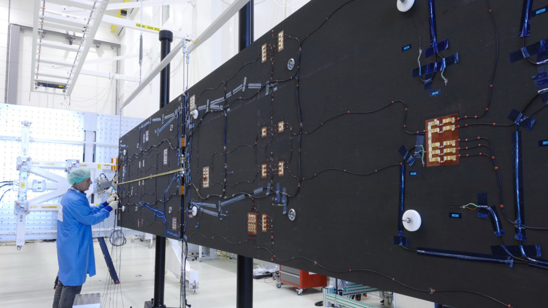
At Ottobrunn these cells are interconnected together into ‘strings’ that run the length of each panel. The bare cells have also have protective cover glass added at this stage, without which they would be quickly tarnished by the radiation and unfiltered sunlight prevailing in orbit.
Test regime
Before delivery to Dutch Space, each panel is thermal vacuum tested at IABG, Germany, followed by the absolute performance measurement and inspection.
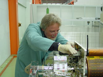
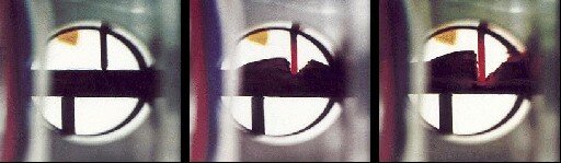
This includes ‘flash testing’ to illuminate all the cells at once to check the arrays meet the set power requirements, as well as electrical luminescence testing, where an electrical current is run through each string to make them glow red, basically reversing the way solar cells usually work. Visual inspection is typically enough to ensure all connections are properly linked.
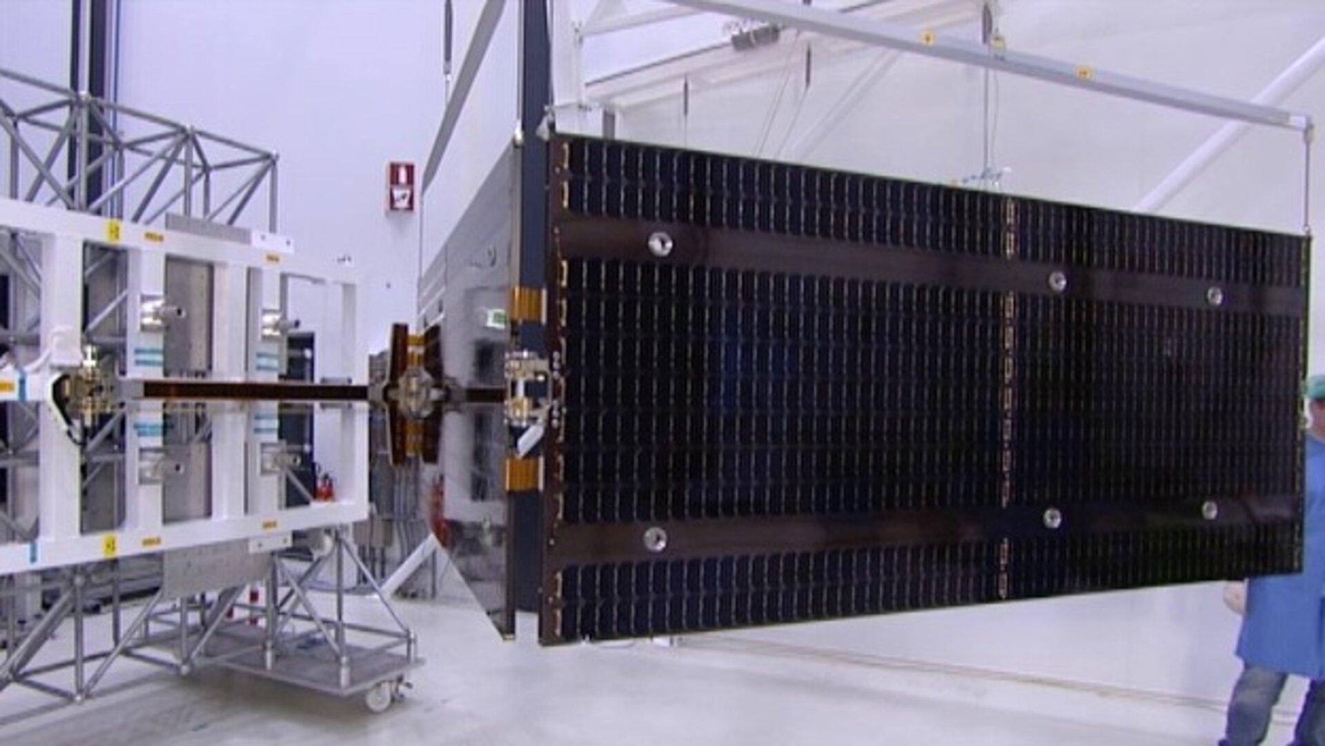
At Dutch Space, the panels from Ottobrunn are integrated together with the mechanisms, typically sourced from local Dutch companies assembled and tested by Dutch Space, into complete solar array wings.
The completed wings are suspended on specially weighted deployment rigs, to compensate for the presence of gravity the 29 kg wings are not designed to endure. Here alignment testing is performed, to check the wings will unfold in a straight line as planned.
“Alignment testing involves the use of reference mirrors and theodolites to check the arrays’ straightness, down to a scale of a tenth of a millimetre at wing tip,” Jan explains.
“In orbit, any bad alignment would be felt by the satellite’s attitude control system, and might even reduce a satellite’s operational life.

Access the video
We also make stiffness tests, which involves hanging weights on a rope on the end of the array, to see what the resulting displacement is. Flex to 100 mm is expected, but not more.”
A large ‘ambient pressure temperature test’ chamber can simulate the rapid temperature swings the arrays will experience as they pass between orbital daylight and darkness. A much smaller cabinet does the same in vacuum conditions, and is used for accelerated lifetime testing to simulate the total life of the arrays, although only for a 50 x 50 cm sample array.
Designing for medium orbit

Dutch Space has been designing its ‘Advanced Rigid Array’ family of arrays for space missions since the 1970s, Jan recalls: “Each mission has different requirements. Low-Earth orbiting arrays such as those for ESA’s Automated Transfer Vehicle need protection from erosive atomic oxygen, found at the top of the atmosphere, while deep space missions like Rosetta or the US Dawn spacecraft require ‘low-intensity low-temperature’ LILT solar cells to go on producing power far from the Sun.
"Galileo flies in medium-Earth orbit, and in the process passes through Earth’s radiation belts. This heightened radiation exposure implies a higher loss factor of cells, which is accounted for with higher capacity at the start. We design solar arrays based on their ‘end-of-life’ performance – how can we ensure they will still meet mission requirements after 12 years in orbit?”
Galileo’s solar arrays are also designed to guard against potential harmful electrostatic discharge – a spark caused by the build-up of static – by introducing gaps any charge cannot traverse, as well as other voltage safeguards.
“As a safety margin, Galileo’s arrays can go on operating satisfactorily with the loss of one complete string of cells.”
The completed arrays are sent on to Full Operational Capability (FOC) prime contractor OHB in Bremen, Germany for integration onto the satellites. Although this is not quite the end of the story for Dutch Space.
Cut-off point
“We have a 100% record of successfully deployed wings in space and we’d like to keep it that way,” Jan comments. “So we provide training to our customers on handling and storing the wings, and especially in working with our unique hold-down system that keeps the solar arrays stacked on either side of the satellite during launch.”
The panels are delicate, composed of just four layers of carbon fibre, and would break easily if struck hard. They are therefore tied tight against the satellite during the violence of launch.
The Kevlar restraint cables are then severed by ‘thermal knives’, with two in place per each hold-down point.
“The Kevlar is weakened gradually instead of suddenly snapping,” Jan explains. “This reduces the amount of shock the arrays experience, compared to the pyros or unwinding rods that other companies use. The arrays then unfold gradually due to springs in the hinges, the process taking a few minutes in all.
“But the system depends on correct tensioning at the outset, which is why we like to be there in person for this point.”
Lessons learned
Dutch Space is well ahead on its Galileo obligations, with 88 substrate panels manufactured and 72 panels equipped with solar cells ready for wing integration. They are carefully stored in gaseous nitrogen until needed, separately from each other for the most part, with integration performed before delivery.
“Our continued involvement with Galileo has been very important to the company,” reflects Jan.
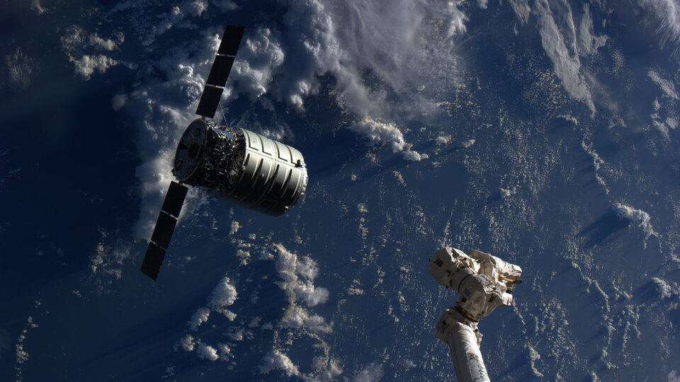
“Dutch Space has worked on batch production previously, such as with solar arrays for the ATV and the US Orbital company’s Cygnus supply vehicle to the International Space Station, but the scale of Galileo is even larger.
We have had a valuable learning curve, finding ways to optimise our production flow and working methods so that we’ve been able to reduce the time needed by 50% from the initial satellite to the latest. And all the things we learn should make us leaner and cheaper for future one-off missions as well.”