AMSU-A1 channels
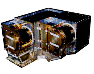
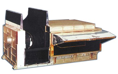
The Advanced Microwave Sounding Unit (AMSU-A1) consists of twelve V-band channels (3 - 14) and one W-band channel 15 and associated circuitry. It has two scanning reflectors: the lower antenna (farthest from Earth in flight) is designated A1-1 and provides inputs to channels 6 and 7, and channels 9 - 15; the upper antenna (closest to Earth in flight) designated A1-2 provides input to channels 3 - 5 and 8.
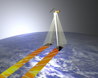
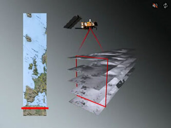
At each channel frequency, the antenna beamwidth is a constant 3.33° ± 10% (circular, at half power point). Thirty contiguous resolution scenes are sampled in a stepped-scan fashion every eight seconds.
AMSU-A1 radiometer characteristics are illustrated in the table below:
| Centre frequency (MHz) | Bandwidth (MHz) | Centre frequency stability (MHz) | |
|---|---|---|---|
| 3 | 50300 |
180 (2 pass-bands) |
± 10.0 |
| 4 | 52800 |
400 (2 pass-bands) |
± 5.0 |
| 5 | 53596 ± 115 |
170 (2 pass-bands) |
± 5.0 |
| 6 | 54400 |
400 (2 pass-bands) |
± 5.0 |
| 7 | 54940 |
400 (2 pass-bands) |
± 5.0 |
| 8 | 55500 |
330 (2 pass-bands) |
± 10.0 |
| 9 | 57290.344 = Flo |
330 (2 pass-bands) |
± 0.5 |
| 10 | Flo ± 217 MHz |
78 (2 pass-bands) |
± 0.5 |
| 11 | Flo ± 322.2 MHz ± 48 MHz |
36 (4 pass-bands) |
± 1.2 |
| 12 | Flo ± 322.2 MHz ± 22 MHz |
16 (4 pass-bands) |
± 1.2 |
| 13 | Flo ± 322.2 MHz ± 10 MHz |
8 (4 pass-bands) |
± 0.5 |
| 14 | Flo ± 322.2 MHz ± 4.5 MHz |
3 (4 pass-bands) |
± 0.5 |
| 15 | 89.0 GHz |
3000 (2 pass-bands) |
± 130.0 |
|
Temperature sensitivity NEDT (K) | Calibration Accuracy (K) | Polarization | -3 dB Stop Band (SB) fc ± SB (MHz) | |
|---|---|---|---|---|
| 3 | 0.4 | 1.5 | V | 10.0 |
| 4 | 0.25 | 1.5 | V | 10.0 |
| 5 | 0.25 | 1.5 | H | 30.0 |
| 6 | 0.25 | 1.5 | H | 10.0 |
| 7 | 0.25 | 1.5 | V | 10.0 |
| 8 | 0.25 | 1.5 | H | 10.0 |
| 9 | 0.25 | 1.5 | H | 10.0 |
| 10 | 0.4 | 1.5 | H | 178.0 |
| 11 | 0.4 | 1.5 | H | 256.2 |
| 12 | 0.6 | 1.5 | H | 292.2 |
| 13 | 0.8 | 1.5 | H | 308.2 |
| 14 | 1.2 | 1.5 | H | 316.2 |
| 15 | 0.5 | 2.0 | V | 500.0 |
V : Polarization vector is parallel to scan plane at nadir
H : Polarization vector is perpendicular to scan plane at nadir