AVHRR components
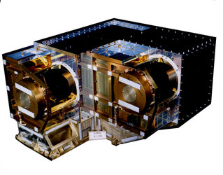
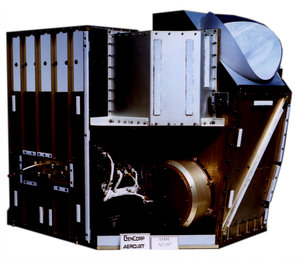
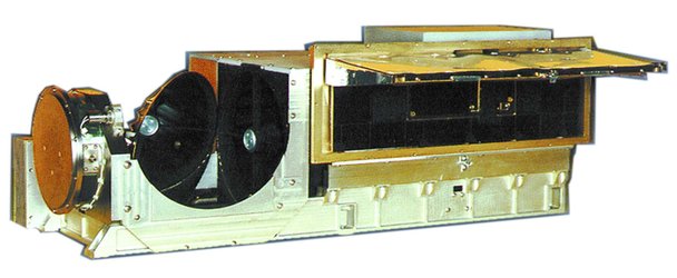
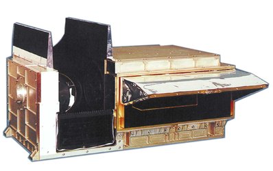
The AVHRR/3 consists of one unit with the following modules:
- Scanner Module
- Electronic Module
- Electronic Calibration
- Radiant Cooler Module
- Optical Sub-system
- Baseplate Unit
Scanner Module
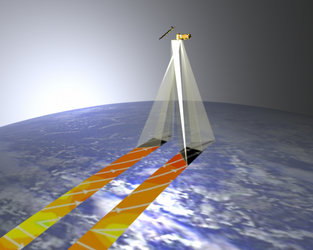
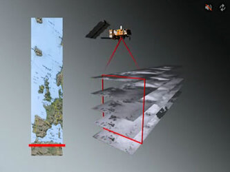
This module includes the scanning motor, the Beryllium mirror and the scan motor housing. The scan mirror motor is an 80-pole two-phase hysterisis synchronous motor or a brushless DC motor. It rotates at a constant 360 rpm rate. This causes the IFOV (Instrument Field of View) to scan scenes from space, through Earth, towards Sun direction.
Electronic Module
This module designates the individual electronic circuits that make up the AVHRR/3 electrical system.
Electronic Calibration
The AVHRR/3 has two electronic calibration functions:
- continuous ramp calibration mode (RAMP-CAL)
- commandable voltage calibration mode (VOLT-CAL, this one is not normally used in-orbit)
The RAMP-CAL is used to verify the linearity and gain of the instrument Analog-to-Digital (A/D) converter and amplifier electronics. The ramp calibration signal increases one step per revolution of the radiometer scanning system. A ramp is generated every 1024 scans. The direction of increase of the ramp is in the direction of increasing the radiance in each channel (i.e. low-to-high counts in the visible channels, and high-to-low counts in the infrared channels).
The VOLT-CAL mode eliminates the detector signals and provides a three-point voltage calibration of the A/D converter and amplifier electronics. This is used mainly for troubleshooting in-orbit.
Radiant Cooler Module
The three thermal infrared detectors are cooled by a two-stage passive radiator. They are mounted on a cold patch that has a 144 cm² (22.4 sq. in.) radiating area. This patch cools to less than 98K with no control power. During nominal operation, its temperature is controlled at 105K.
The radiant cooler module consists of the:
- cooler housing
- first stage radiator
- patch or second stage radiator
- cooler door
The door on the cooler assembly insulates the radiator from Earth direct thermal input. The door is released after the initial orbital outgas period. During the outgas / decontamination period, the cooler temperature rises to approximately 300K.
The cooler door deployment mechanism is similar to a caging mechanism. Power is required only to release the shield by solenoid action after the spacecraft achieves operational orbit (single-shot solenoid, actuated by a spring driven deployment mechanism).
Optical Sub-system
The optical sub-system consists of a collecting telescope and a relay optics unit. Its characteristics are summarised as follows :
- Instantaneous field of view : 0.0745° (square, approx 1.1 km)
- Earth view pixels per scan : 2048
- Swath (with respect to the nadir direction) : ± 55.37°
Baseplate Unit
The baseplate unit is the common structure on which all other modules are mounted. It is the physical interface to the satellite. It is also the major interface for the radiative thermal control of the instrument.


