MHS Description
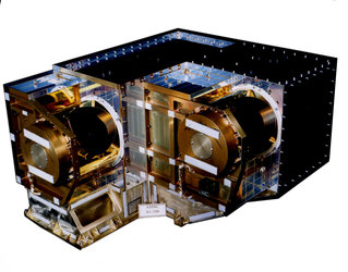
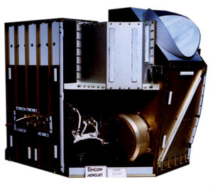
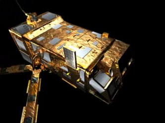
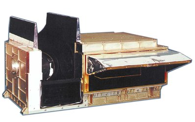
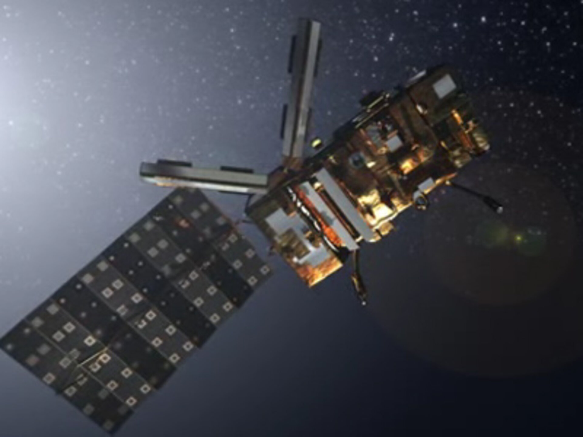
The Microwave Humidity Sounder (MHS) instrument is a compact five-channel self-calibrating microwave rotating radiometer weighing around 63 kg. Occupying a 0.8-metre cube, it is positioned on the nadir-facing side of the MetOp satellite and is designed to scan perpendicular to the direction flight (across track) at a rate of 2.67 seconds per scan. The swath width of the scan is approximately +/- 50°. The scan is synchronised with the AMSU-A1 and A2 instruments, with MHS performing three scan cycles for every one performed by the AMSU instruments.
The MHS incorporates four receiver chains at 89 GHz, 157 GHz and 190 GHz, with the 183 GHz data sampled in two discrete bands to provide the five channels. The separation of the four target frequencies is achieved by quasi-optical elements integrated in the received subsystem.
Receiver
Detectors
The MHS contains four detectors, one per channel. The fifth channel is achieved by splitting the 183.311 GHz signal into two channels, each with a different bandwidth.
| Centre Frequency (GHz) | Bandwidth (max., GHz) | |
|---|---|---|
| CH 1 | 89.0 | 2.8 |
| CH 2 | 157.0 | 2.8 |
| CH 3 | 183.311 | 2 x 0.5 (Dual Side Band) |
| CH 4 | 183.311 | 2 x 1.0 (Dual Side Band) |
| CH 5 | 190.311 | 2.2 |
Scan mechanism

Scanning
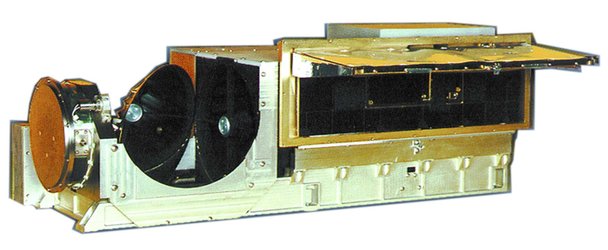
An offset paraboloid reflector is mechanically rotated in order to provide a scan of the Earth, the on-board calibration (hot) target and the deep space (cold) target. The Earth is scanned in a direction perpendicular to the direction of the satellite’s path (i.e. across track scanning).
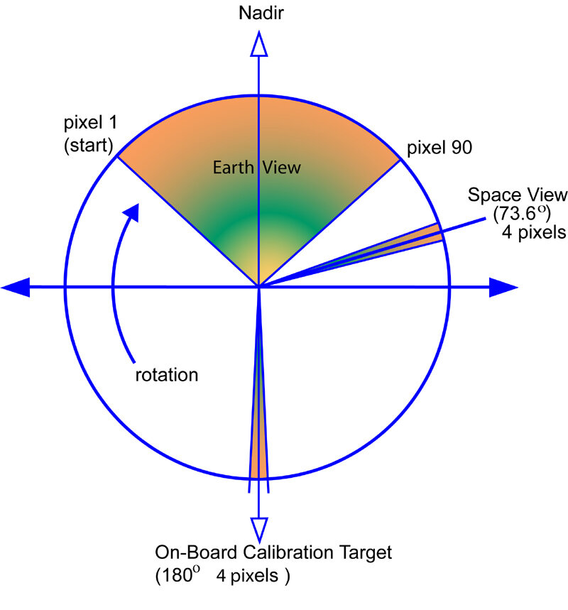
The reflector rotates once per 2.667 seconds, with a slower rate of rotation when viewing the Earth and targets but at a faster rate in between. The scan motion of the reflector is fully compensated for momentum by a counter-rotating flywheel to minimise the disturbances to the satellites' Attitude Control system. This flywheel is controlled independently to the reflector.

The Field of View
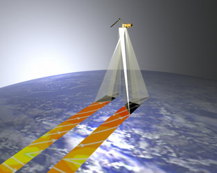
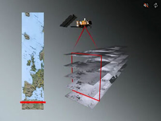
The Field of View (FOV) of the instrument is circular, and the 'footprint' is approximately 16 km in diameter at the Earth's surface in the nadir direction. The MHS instrument takes 90 separate data samples (pixels) for each of the five channels during each scan across the Earth view (see section Overview). Each subsequent scan will provide Earth view data from a swath immediately adjacent to the previous scan. This 'Scan Mode' is the normal operational mode of the MHS. However, the MHS can also be operated in a Fixed View Mode. In this mode, the reflector remains in any defined static position, throughout all data sampling.
This picture shows a single footprint disc on the Earth's surface, which effectively travels in a direction parallel to the satellite track as the satellite moves over the surface. A single 16 km wide track is sampled only when the scan is pointed directly at the Earth (nadir); it becomes wider further away from the nadir.
Electronic Equipment
Instrument control
A microprocessor in the MHS provides extensive flexibility in overall instrument control. In particular the microprocessor and its application software:
- execute commands
- monitor telemetry
- control the scan mechanism (reflector and flywheel)
- control science data sampling
- format science data into standardised packets (i.e.where the layout of data in these packets has been predefined)
Failure detection is also included, whereby the microprocessor is able to put the instrument into a low power 'safe' condition for subsequent diagnostic analysis and recovery by the Ground Station team.