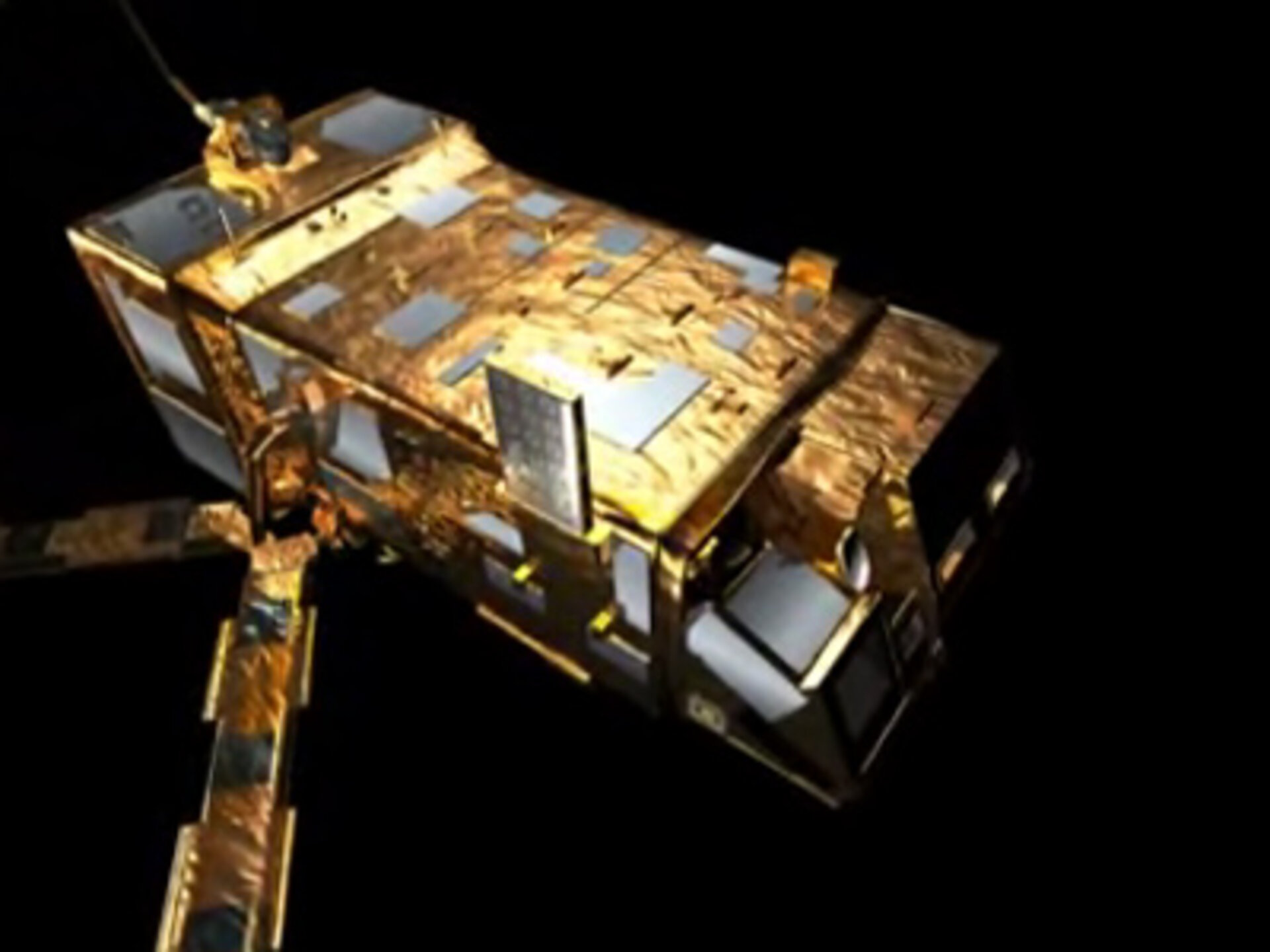
GRAS instrument design
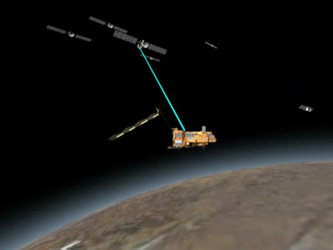
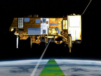
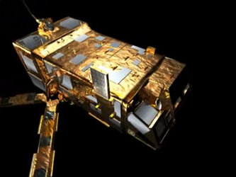
The entire GRAS (Global Navigation Satellite System Receiver for Atmospheric Sounding) instrument weighs about 30 kg and comprises three antenna-receivers positioned separately on MetOp. One of the antennae, the GVA antenna, points in the velocity direction of the satellite, another, the GAVA antenna points in the anti-velocity direction, and the smaller GZA antenna points zenith.
The GVA and GAVA antennae are both rectangle-shaped, covered by a single layer of insulation. They carry 18 elements, each targeted to look tangentially through the Earth's atmosphere to receive radio signals from the constellation of navigation satellites. The GVA observes rising occultations and the GAVA observes setting ones. Together, they can connect to up to 12 satellites at any one time (two by the GVA chain, two by the GAVA chain and eight by the GZA for navigation. Therefore, four occultation measurements can be made in parallel, two on each side). Because of the positioning of the GAVA antenna on the MetOp satellite, it is deployed after launch to prevent its field of view being obscured by the ASCAT instrument.
The smaller GZA antenna is used to determine the precise position of MetOp by continuously tracking other GPS satellites.
Technical description
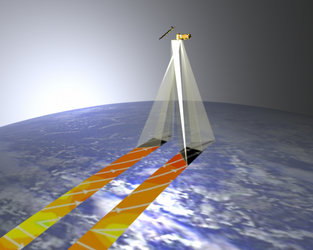
GRAS is a bi-frequency GPS receiver with codeless-mode operating capabilities. A dual-frequency operating instrument is needed for ionospheric correction. The codeless capability is mandatory in order to mitigate the anti-spoofing (encryption of the precise code), which prevents civilian users from benefitting from the P-code on the L2 frequency. The signals of the occulting satellites are received through two antennas (GVA and GAVA). The GVA observes rising occultations and GAVA observes setting ones. Shaped antenna patterns (9 to 10 dB gain) and dedicated radio-frequency front-ends (RFCU) ensure a high sensitivity and the ability to measure at low altitudes in the atmosphere – just a few kilometres – where the atmospheric attenuation due to absorption and diffraction is high.
To track the MetOp satellite's position, the instrument also operates as a navigation receiver. In this context, it receives GPS signals via a third antenna (GZA) with hemispherical coverage, pointing at zenith. It acquires and tracks a set of GPS signals through eight bi-frequency channels having codeless capabilities, and uses a limited-precision navigation solution, using C/A code only, to support the autonomous instrument operation. It also provides the positional data as part of its measurement data to the Payload Module to be transmitted to the ground segment. Within the ground segment, the data is then used to compute the precise orbit of the spacecraft.
Components
The instrument is designed by Saab Ericsson Space in Sweden, supported by Austrian Aeropspace for the application software, the processor boards and the test equipment, SENER in Spain for the design of the deployment mechanism of the GAVA antenna, and GMV in Spain for the Ground Processor Prototype (GPP).
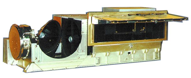
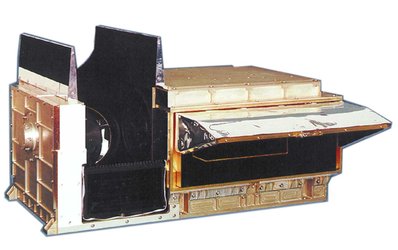
The GRAS instrument consists of :
- 3 antennas (GVA, GAVA and GZA)
- 3 RF Conditioning Units (RFCUs)
- 1 GRAS Electronics Unit (GEU)
Antennae
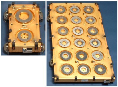
The three antennae point in the satellite's velocity (GVA), anti-velocity (GAVA) and zenith (GZA) directions. The velocity and anti-velocity antennas are phased arrays, each containing 18 patches with a shaped antenna pattern optimised for the occultation of the Earth's limb and its atmosphere.
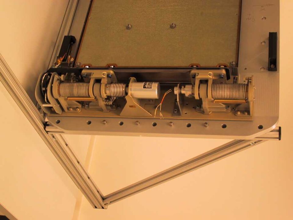
As the GAVA antenna field of view would be obstructed by the ASCAT antenna, the antenna is folded on the -Y panel and deployed after launch by the GAVA Deployment Mechanism (GDM).

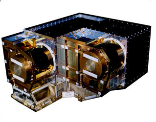
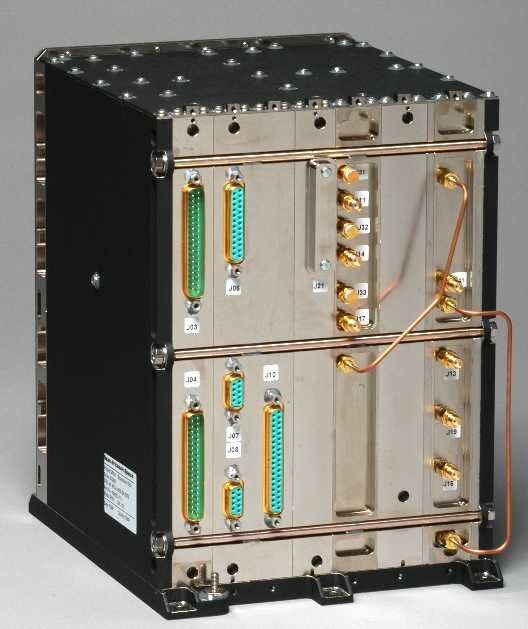
Radio Frequency Conditioning Units (RFCU)
The RFCU consists of two bandpass filters, a low-noise amplifier and a single down-converter stage. The RFC units are accommodated within the Payload Module close to their respective antennas in order to minimise ohmic losses.
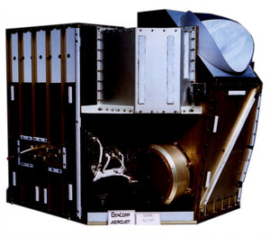
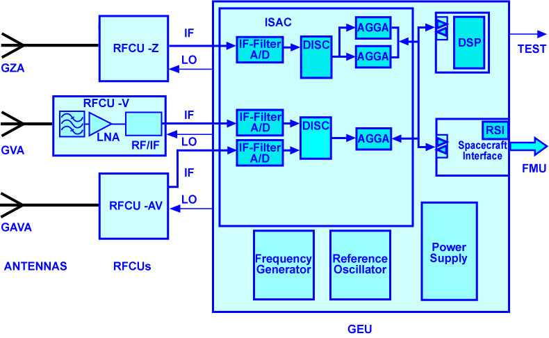
GRAS Electronics Unit (GEU)
The GEU is built around three dedicated Advanced GPS GLONASS ASICs (AGGA) and a Digital Signal Processor (DSP). After filtering and a single-stage down-conversion in the RFCU, the IF signals are digitally down-converted with an 8-bit ADC, and filtered in a DISC ASIC, then sampled at a high rate (141.25 MHz) and delivered to the channel processor. The core of the processor is the AGGA, which simultaneously performs the final down-conversion, de-spreading and correlation of four bi-frequency GNSS channels. It also provides the codeless functionality. It has been developed by the European Space Agency (ESA) and contains functionality for tracking the phase and frequency of code and carrier. The AGGA ASIC provides a number of observables to the DSP, which the latter uses to close the tracking loops and to produce the actual measurement data.
The DISC ASIC converts the 8 bits, 141.25 MHZ samples into 2 bits 28 MHZ samples suitable for the AGGA. The DISC ASIC is developed by Saab Ericsson Space.
The DSP chip itself (TSC 2102OE) has been developed by European space industry under an ESA contract. Its role within the GRAS instrument is to support the Instrument Control Unit (ICU) software as well as the data-processing software (measurement, signal tracking, navigation solution and time management). The Spacecraft Interface (SCIF) board provides the interface between the DSP bus, the satellite OBDH bus and the Formatting and Multiplexing Unit (FMU) of the Payload Module.
An oven-controlled crystal oscillator is used as a reference oscillator with very stable frequency (Allan deviation of 10 - 12) in order to retrieve atmospheric measurements with a high accuracy in the stratosphere. The frequency generator provides the necessary frequencies for down-conversion and clock-signal generation using the reference oscillator. The power supply converts primary power to secondary power for the instrument units.