How are the Antenna Test Facilities equipped?
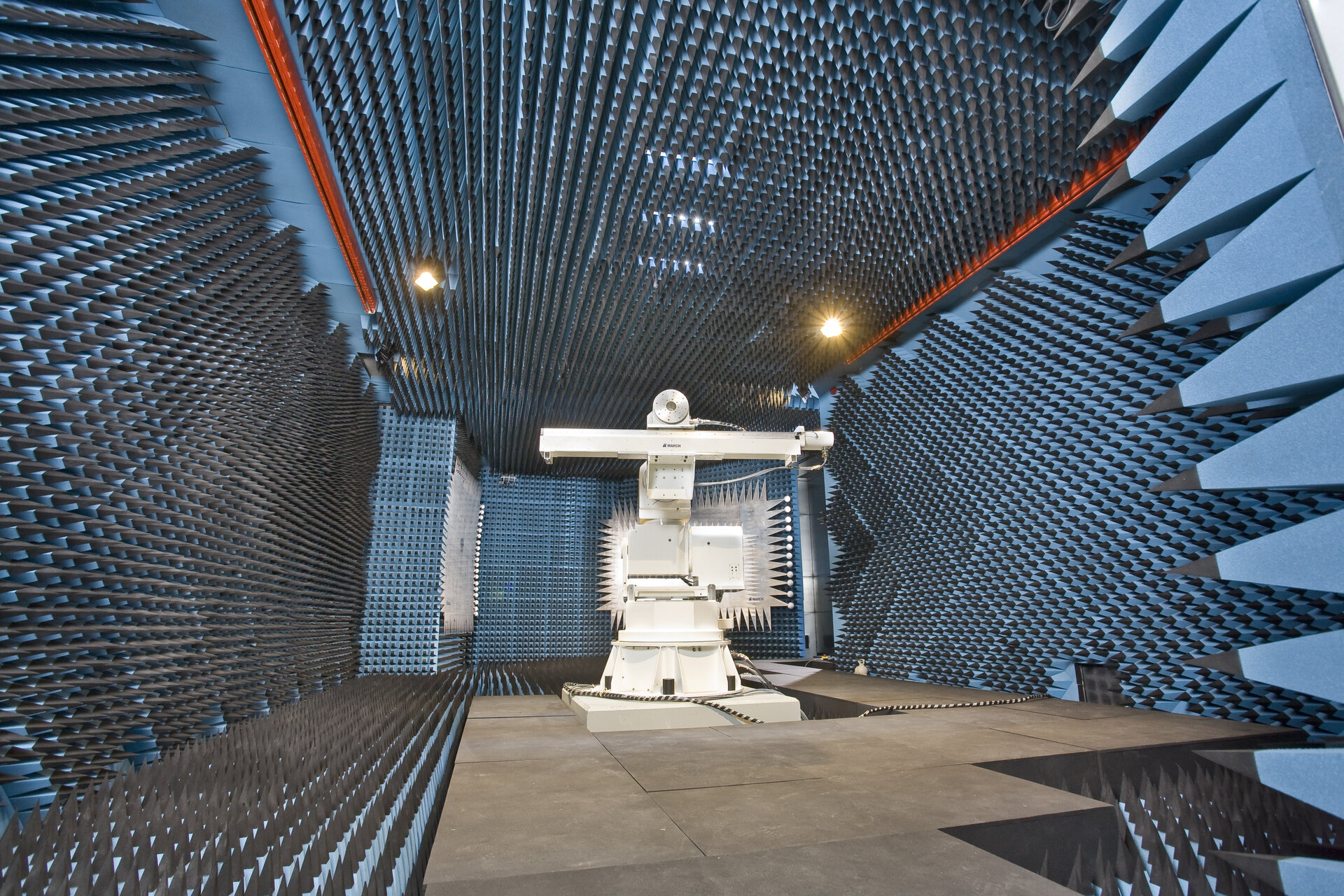
Both the CATR and HERTZ are shielded anechoic chambers with internal foam coatings that absorb reflected radio waves to simulate the boundless nature of space. The metal walls form Faraday cages, blocking all external signals such as TV broadcasts, airplane and ship radars and even mobile call phones.
These two anechoic facilities are complementary: the CATR is 12.5 m long by 8.5 m wide and 4.3 m high, and allows easy access and mounting of small test objects in ambient environmental conditions with testing capabilities between 4 and 250 GHz. In addition, the laboratories have equipment up to 500 GHz with the possibility to perform antenna measurements using Planar Near Field techniques at these frequencies (with an extension to 750 GHz currently in development).
The CATR is referred as compact, though not strictly because of its size. Instead this term refers to a particular design feature: radio waves coming from a nearby source are curved like a pond rippling after a stone is thrown. Radio waves coming from great distances take the form of parallel straight lines converging on infinity. So compact anechoic chambers incorporate parabolic reflectors which are specially shaped to straighten the curvature of the radio waves, artificially creating equivalent conditions to long-distance space transmissions within a relatively small area.
HERTZ is the size of a small sports hall, measuring 25 m long by 16 m wide by 11m high and can incorporate much larger items. In addition, being a ISO 8 clean room (Class 100.000), HERTZ is a state of the art satellite antenna testing facility, allowing the characterization of flight antennas and completely integrated satellites.
HERTZ is a hybrid antenna testing laboratory which combines in the same anechoic chamber a Compact Payload Test Range (CPTR) and a Near Field Range (NFR). Their purpose is to verify in-orbit performance of antennas, payloads and complete satellites with complex antenna farms. The CPTR is a Compensated Compact Range, designed for low cross-polar performance. The CPTR has a frequency range of 3.5 to 20 GHz, meaning that very accurate measurements of communications payloads employing frequency and/or polarisation re-use can be performed.
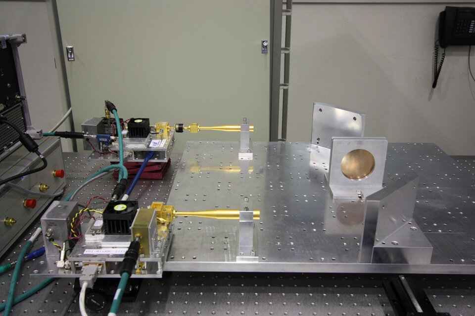
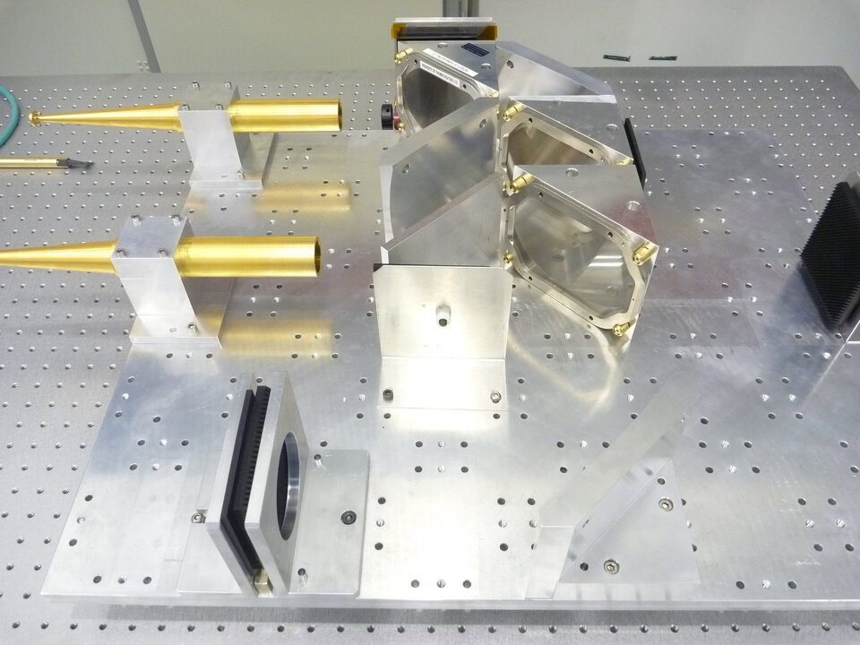
The Near Field Range consists of an inverted-T planar scanner in combination with the heavy duty positioning system for the Device Under Test (DUT). For planar scanning, the DUT does not move and can be even positioned on its own support (e.g. multi-purpose trolley) if required. For spherical and cylindrical near-field scanning, the theta-phi rotation is performed in a roll-over-azimuth configuration.When required , the Microwave Material RF Characterization setup can be integrated in the CATR to provide measurement tools for the determination of complex material properties based on the transmission and reflection properties of a sample under test. It is a quasi-optical free space test facility that allows polarization measurements in transmission and reflection (both monostatic and bistatic) from 8 to 110 GHz. This facility enables the characterization of materials for antenna radomes, reflectors, Electromagnetic Band Gap structures as well as Frequency /Polarisation Selective Surfaces (FSS).
The (Sub) mm-wave Material RF Characterization setup allows the characterization of dielectrics, ferrites, reflective surfaces and a variety of printed structures, such as FSS, CPSS and half-wave plates. Co-polar and cross-polar components of the transmission and reflection properties of samples under test can be determined between 50 and 500 GHz.