Mechanical engineers helping steer Vega’s course
As well as such ‘big picture’ activities in the course of Vega development, the Structures and Mechanisms team also drilled down to particular subsystems.
This included work on the development and qualification of the electromechanical actuators used for the thrust vector control system of the second, third and fourth stages, controlling their thrust direction during flight.
Used for the first time on a European launcher - in place of the bulkier hydraulic thrust vector control system employed by Ariane 5 - each stage has two actuators for orienting the rocket nozzle, an electronic control unit called the Integrated Power Distribution Unit (IPDU) and a lithium-ion battery, all linked by a cable harness.

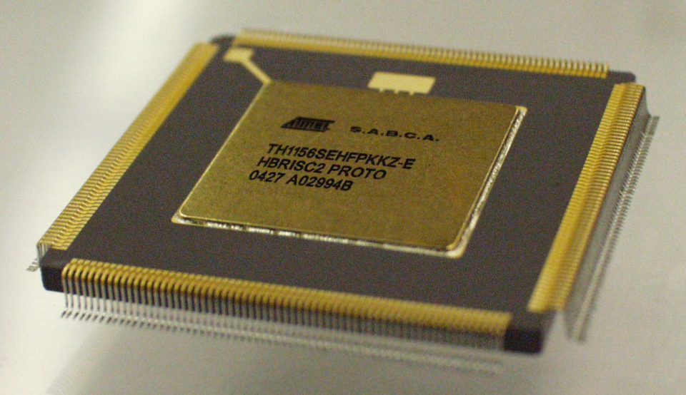
The Structures and Mechanisms division previously oversaw development of the HBRISC2 processor at the heart of this system, capable of maintaining simultaneous control of the pair of actuators while also being hardened against the space radiation effects that begin to manifest as Vega rises beyond the protection of the atmosphere.
“With the thrust vector controls mounted on the solid rocket motor structure close to the interstages, the shock induced by each stage separation was a mechanical challenge to the system,” Torben added.
“We worked hard to reproduce this using results from pyrotechnic shock tests, division experts helping industry to set up the testing in order to achieve the correct input levels.
“These demanding conditions led to various problems with thrust vector control components where the root cause had to be pinned down. Members of our team became integrated with the Vega project team throughout the qualification and test campaign.”
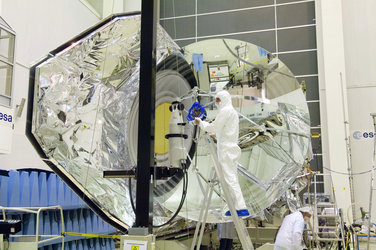
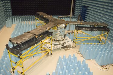
Along similar lines, the team helped to define the shock environment induced by the launcher upon its satellite passengers, the putting together of a test method to reproduce it, and the identification of methods to deal with it, starting with LISA Pathfinder, due to fly next year.
Subsystem studies

The division also worked to analyse structural vulnerabilities of the oxidiser tanks of Vega’s sole liquid-fuelled stage, the topmost Attitude Vernier Upper Module (AVUM) stage, carrying out an independent study of fracture control measures implemented for the tanks.
This resulted in follow-up recommendations to measure residual stresses induced by the welding process, and improved inspection methods to look for potential cracks in a non-destructive way, subsequently implemented by industry.
The team additionally performed various CAD-based configuration studies of various parts of the launcher, notably for the dispenser used to deploy Vega’s multiple CubeSats into orbit and a study of ways that various internal units could be accessed for repair or replacement, even as the vehicle stands ready on the launch pad.
Fire down below

While the Structures and Mechanisms division worked on Vega’s structure and moving parts, the Propulsion and Aerothermodynamics division concerned itself with the extreme conditions prevailing in Vega’s immediate vicinity: the high-speed motion of gases within its solid rocket motors as well as characterising Vega’s rocket plume as it leaves its rocket nozzle.
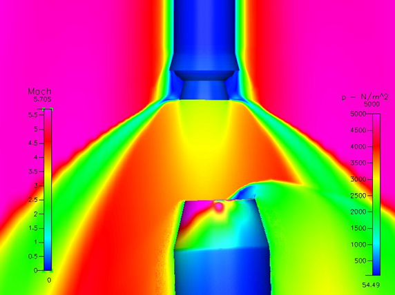
ESA’s Propulsion and Aerothermodynamics experts assisted the Vega team in various ways, including producing complex fluid dynamics (CFD)-based simulations of the staging process, seeking to estimate the optimal separation distance before the next stage engine started up, to prevent rocket plumes reflecting back up onto the upper composite or inducing flight instabilities.
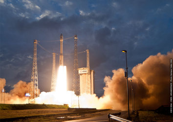
Protecting the pad
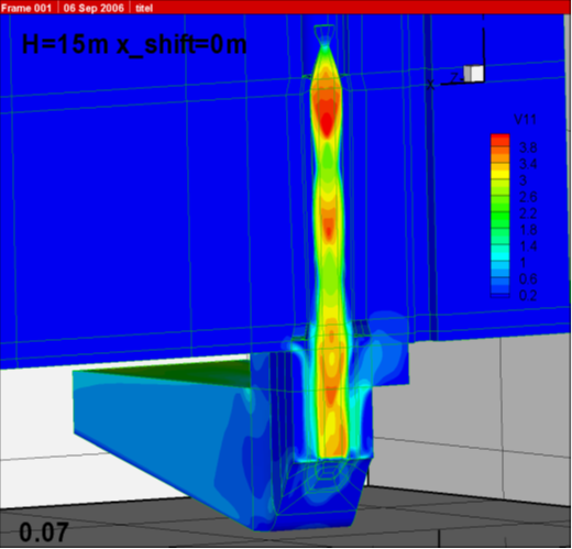
Similarly, the section investigated the impact of the Vega engine plume at the moment of launch from the concrete surroundings of its ELA-1 pad, as its solid rocket motor produced a shower of burning propellant particles.
A model of the pad, including the flame trench intended to vent this exhaust away, was created along with a model of Vega itself.
“Modelling gave us the detailed flow structure within the plume, showing its temperature distribution and how it evolved over time,” commented Giorgio Saccoccia, division head.
“CFD modelling was coupled with other engineering methods such as uncertainties assessment to derive as detailed a picture as possible of the launch for the Vega team.”
The inflight plume of Vega’s Z9 third stage was also modelled in detail to assess the different particle sizes and temperatures of its various segments, in order to characterise its ‘radiative flux’ back to the top of the launcher and to assess whether this might tip the temperature of the payload above its set limits.
Riding on top: Vega’s autopilot

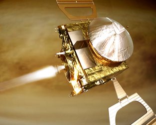
The Propulsion and Aerothermodynamics division gave special support to the design and development of the AVUM upper stage.
As much a space vehicle as a launcher stage, AVUM hosts the avionics ‘brain’ of Vega and the Roll and Reaction Control System (RACS) that performs roll control for the entire launcher throughout its flight and corrects any axial instability owing to variations in solid motor performance.
AVUM’s liquid-fuelled engine also takes over attitude control for the final leg of the flight to orbit, its engine reignitable up to five times to deliver satellites into a wide variety of orbits before reorienting itself for a suicide dive deorbit.
The team’s support focused on the propellant management system serving RACS. The challenge here was to ensure the system had the fine pointing capacity to point satellite payloads in just the right direction in the period before separation, while still yielding the raw power to keep the entire 130 tonne launcher oriented correctly during the earlier stages of flight.
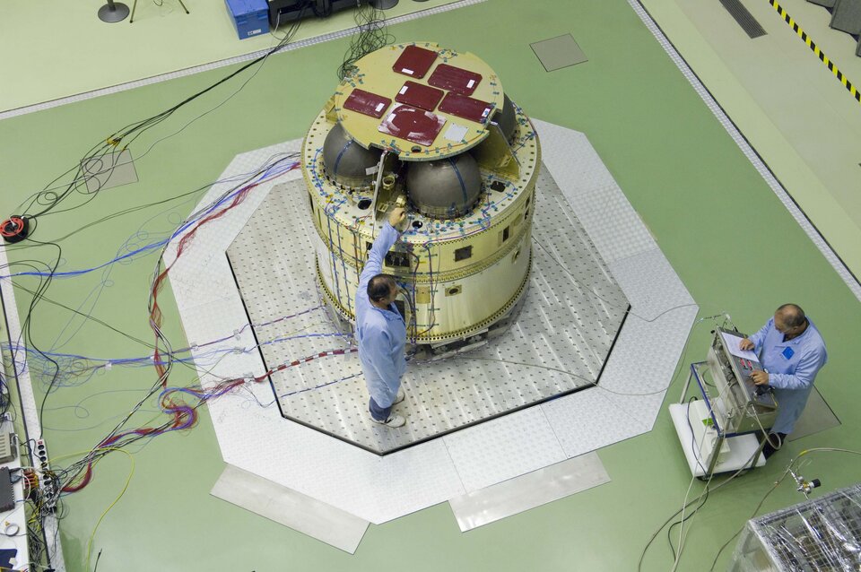
They went on to support testing of an engineering model of AVUM, the Upper Composite Mechanical, which as well as vibration testing underwent loading and unloading activities with a non-toxic analogue of hydrazine and oxidiser – glycerin and water – at ESTEC’s Test Centre.
Post-flight analysis
Since Vega’s initial flight on 13 February this year ESA’s Mechanical Systems department has been busy supporting the cross-checking of the launcher’s telemetry with their own model outputs, to sharpen the accuracy of the models to serve the four test flights to follow.
"The detailed analysis of the flight data, the so-called Level 1 analysis, has confirmed that the Vega maiden flight has been flawless," said Stefano Bianchi, ESA's Vega programme manager.
"All the engineers who have been working for years at ESTEC on verification, modelling and cross checks of the Vega launcher, can be proud of this great result. ESA teams have really been one of the pillars of this great European success."
The mechanical lessons from Vega can also be applied to future developments of Ariane 5 of course, and also offer a way forward for ESA’s Next Generation Launcher, being considered for around 2020.
| |
|
| |
|