
Innovative Spacewire-based harness-reduction technique for the LOFT CDF study
TEC-EDD provided expertise for the definition of the Data Handling System (DHS), based on some initial mission requirements. The main elements of the DHS were the on-board computer (OBC), including the processor modules (PM), the telemetry/telecommand (TM/TC) modules, the reconfiguration module (RM), the I/O modules and power supplies. There were also dedicated Instrument Controller Unit for each instrument. These PDHUs are responsible for interfacing the instruments to their local mass memory units and to the OBC, but also for configuring the instruments and collecting housekeeping data. In addition the Instrument Controller Units support science data compression and processing, e.g. image compression (in the case of the WFM instrument).
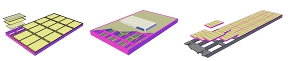
One of the challenges in the design of the DHS was the interfacing of the detector panels in the LAD instrument to the main platform (PDHU, and OBC). The length of each of the six detector panels (more than 3m) and the very large number of detectors presented a significant challenge in terms of harness: all these detectors, via their front end electronics boxes, had to be powered, and also communicate with the PDHU for the instrument, and in turn with the OBC. The overall structure of each detector panel is shown In Figure 1 above.
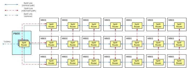
The data to be transferred between PBEE - DHU, and DHU - OBC, include science data, housekeeping, TC, and PPS (clock signal). The proposal was to use a single dedicated SpW link, rather than separate lines, to bundle the transfers of all four types of data. The panel harness architecture shown in Figure 2 is based on this concept, in which the MBEEs are connected in a "daisy chained" manner using SpW links and routers.
The advantages of this architecture are that it reduces the length of the cabling required, plus it simplifies the design of the PBEE unit and makes it more robust: only two SpW routers are required in the PBEE, in a redundant configuration, hence reducing the points of failure. If the baseline architecture was used, in which the routing is centralised in the PBEE, with dedicated SpW links running from the PBEE to each of the 21 MBEEs, then 8 SpW routers (4 x2 for redundancy) would be needed in each PBEE, significantly increasing the complexity and the points of failure in the module.
The resulting SpW network also provides some inherent redundancy, in the sense that if any of the MBEEs is to fail the data traffic from the other MBEEs in the same column could be rerouted around the malfunctioning module using SpW path addressing. Furthermore, if the SpaceWire-D protocol is used for the data transfers determinism can be introduced in the timing of the data transfers, which could be beneficial especially for the distribution of the telecommands.
Overall DHS architecture
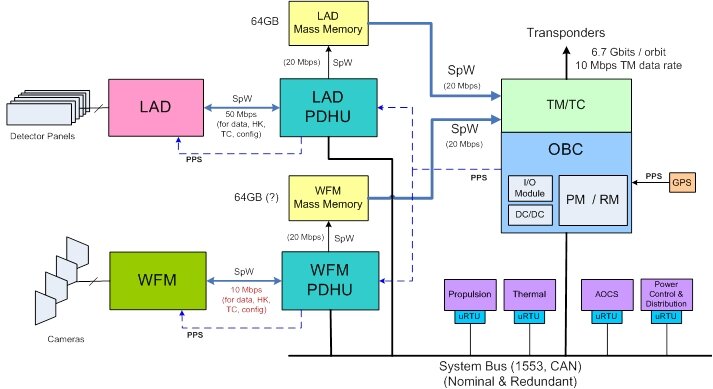
The overall DHS architecture proposed for LOFT was based on the use of use separate, dedicated PDHUs for each instrument, and a central OBC. The dedicated Instrument Controller Units would allow self-containment, and independent, decoupled development for each instrument. For simplicity and uniformity the same PDHU design could be used for both instruments. The overall LOFT DHS architecture is illustrated in Figure 3.
The DHS architecture consists of the two LOFT instruments (LAD and WFM), each with a dedicated PDHU and Mass Memory Unit, the OBC with the processor, reconfiguration, I/O, TM/TC and DC/DC conversion modules, and the micro-RTUs to interface the rest of the subsystems with the main command and control bus (system bus, in nominal/redundant configuration).