
Optimised Antenna Elements Position and Dimensions
| 619 - Abstract: |
| The European Space Agency has developed a technology which describes a method and a computer software product with which antennas are designed. Using this method and software, the positioning of the elements, their dimensions and number are optimized thereby minimising the overall consumption, complexity and dimensions. Potential fields of applications are Earth observation, security and telecommunications (phased arrays) for broadcasting. Licensing agreements are sought. |
Description
This technology describes a method and a computer software product to design antenna arrays. Using this method and software, the position of the elements, their dimensions and number are optimized, thereby reducing the overall consumption, complexity and dimensions.
Array antennas provide significant advantages in flexibility and versatility with respect to conventional antennas. The reason is because the array pattern may be completely reconfigured, changing the complex feeding excitations (in amplitude and phase). The array excitation can be accurately controlled. In order to keep the cost and complexity of the antenna under control, it is crucial to reduce the number of active elements and simplify the beamforming network.
The proposed methodology provides a simple, yet effective, method to design and manufacture array antennas by exploiting all available degrees of freedom of the array (i.e. positions of the elements, dimensions and number of elements). This technology uses the elements’ position jointly with the element dimensions to drastically reduce the costs and complexity of the array antenna while maximising the aperture filling factor and the associated aperture efficiency and directivity. The design method is fully deterministic and analytical.
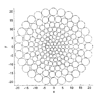
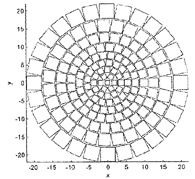
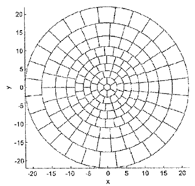
These pictures (right), show exemplificative layouts of arrays designed accordingly to the present methodology and employing radiating elements with different apertures. (e.g. a) circular; b) square; c) annulus sector).
The proposed method can be summarised in the following steps:
- Design phase: during this phase an array layout of an array antenna is synthesized and radiating elements are designed to be arranged optimally;
- Definition of a continuous reference aperture: this can be done by subdividing the continuous reference aperture into a plurality of elementary cells with assigned power levels;
- Identification within each of the above mentioned elementary cell, a position for at least one maximum efficiency radiating element; determining the size of an aperture field amplitude of each maximum efficiency radiating element. In this way, a variation of cumulative field distribution of the resulting array antenna aperture over each reference aperture over the same elementary cell, is subject to size constraints
- Manufacturing phase: the array antenna is physically made. It comprises the radiating elements arranged according to the array layout identified in the previous step.
Innovations and advantages
The proposed innovative methodology for array antennas design is advantageous with respect to other technologies mainly because it allows:
- Effective reduction in the number of Amplifiers and Radiating Elements, thanks to the joint use of positions and dimensions of the radiating elements.
- Optimal power utilization efficiency in the amplification stage. All the on-board High Power Amplifiers (HPAs) may work near saturation, so high DC-to-RF power conversion efficiency and full advantage of HPA power-handling capabilities are achieved.
- Low complexity of the antenna sub-system. In one implementation based on a beamforming network, the distribution network is composed of simple power splitters of equal division ratio; in a second implementation based on the Discrete Lens concept, the beamforming network is not required.
- Manufacturability. All the components used in the proposed antenna architecture can be based on already qualified space technologies.
Reduction of the cost of both manufacturing (number of elements) and power consumption.
Domain of application
The antenna design methodology was conceived for space missions. However it may also be useful for the following applications:
- Earth observation: mounted on an aircraft for weather forecast, soil moisture, ocean salinity, ozone mapping, vast areas monitoring, deforestation monitoring, monitoring natural disasters such as hurricanes, oil spill detection, etc.
- Security applications: mounted on an aircraft (both manned and unmanned) for applications such as reconnaissance, surveillance and targeting among, or it may even be used for electronic jamming activities. It may be also be used for radar applications.
Telecommunications: in order to synthesize the most appropriated radiating pattern (phased arrays) for each application in cellular systems base stations and broadcasting.
