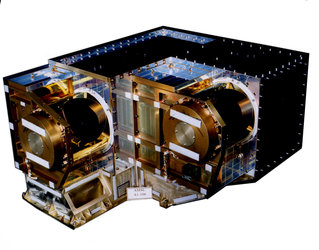
AMSU-A2 components
The Advanced Microwave Sounding Unit (AMSU-A2) consists of one unit with the following modules:
- Antenna / Drive / Calibration Subsystem
- Receiver Subsystem
- Signal Processor Subsystem
- Structural / Thermal Subsystem
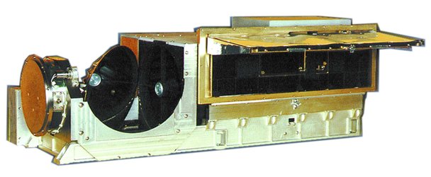
Antenna / Drive / Calibration Subsystem
This subsystem consists of a conical corrugated horn-fed shrouded reflector, multiplexer, closed loop antenna scan drive assembly and closed path calibration assembly.
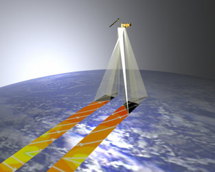
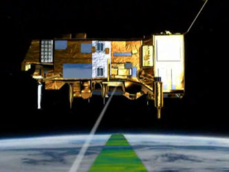
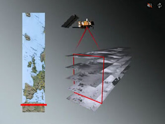
During an eight second scan, the reflector observes:
- 30 Earth viewing scenes
- the cosmic background (about 3K, cold calibration)
- an internal warm calibration load (about 300K)
The sampling interval is 3.3333° and the overall swath, with respect to the nadir direction is ± 48.333°.
During rotation, the shroud shields the warm load from reflections and ensures maximum decoupling of the load to the antenna feed during calibration observations.
A complete end-to-end calibration is achieved by a complex internal calibration procedure. Here the instrument scan mirror dwells to different scan positions which represents warm and cold references. The warm calibration reference is realised by an internal warm calibration load whereas for the cold reference a view to deep space is made. Knowledge and accuracy of warm calibration load brightness temperature is better than ± 0.2K.
Closed loop antenna scan drive provides beam-pointing accuracy within ± 0.2°. Precise antenna beam position information is provided in the measurement / scientific data. AMSU-A2 has one rotational scanning reflector with momentum compensation.
Receiver Subsystem
All AMSU-A channels are configured as total power super heterodyne receivers. Each channel provides:
- RF (Radio Frequency) to IF (Intermittent Frequency) conversion
- IF amplification
- filtering of the frequency bands
- detection
- video amplification
Isolators precede the RF to IF conversion, preventing the possibility of local oscillator power leaking from the mixer, through the antenna and being reflected from the warm load back into the receiver. Fundamentally pumped double balanced mixers are used for all channels.
Signal Processor Subsystem
This subsystem consists of the following:
- video processor
- analog-to-digital converter
- microprocessor
- memory
- FIFO (First in, first out buffer)
- timing and control circuitry
- DC/ DC converters
- spacecraft interface circuitry
Spacecraft interface circuits provide the spacecraft telemetry system with the following:
- all channels of radiometric data
- antenna position data
- thermometric temperature of the warm calibration load and RF shelfs
- digital and analog housekeeping data
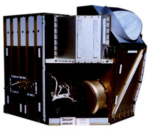
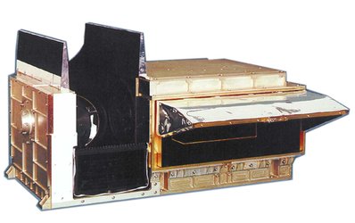
Structural / Thermal Subsystem
A modularised structural configuration incorporating passive thermal control is used. The mechanical / structural assembly is a box-type structure with aluminium panels to integrate the various subsystems. The enclosure and internal structure is designed to eliminate radio frequency interference. The AMSU-A2 utilises second surface silvered Teflon tape, gold tape and multi-layer insulation for passive thermal control.
| Scan cycle | Description | Sequence duration | Total |
|---|---|---|---|
| Earth scan |
30 steps of < 0.2 s (96.667°) |
5.965 s | 5.965 s |
|
Slew 1 to Cold Cal. (35.0° for Cal. #1) |
0.205 s | 6.170 s | |
| Space view dwell | 0.370 s | 6.540 s | |
| Calibration |
Slew 2 to Warm Cal. (96.667° from Cal. #1) |
0.370 s | 6.910 s |
| Warm load dwell | 0.370 s | 7.280 s | |
| Slew 3 to Scan Position #1(131.667°) | 0.460 s |
7.740 s (<8 s) |