Characterization of receivers
The characterization of receivers involves the following recommended steps:
- Step I: Measurements calibration
- Step II: Measurements characterization
- Step III: Clock characterization
- Step IV: Antenna calibration
These procedures are described below:
Step I: Measurements calibration
This calibration process covers, the estimation of the differential hardware delays between different channels either processing signals in the same band or in different bands. The following three type of analysis are to be carried out:
- Code phase coherence between channels on the same frequency
- Code phase coherence between channels on different frequencies
- Carrier phase double differences integer ambiguities
Step II: Measurements characterization
The GNSS receiver response, under different types of signal perturbations is analyzed. The existing laboratory equipment makes it possible to define and control all receiver inputs, including any potential perturbation such as multipath, interference, or dynamic stress. The perturbations can be defined and combined freely in order to reproduce the scenarios of interest, either representing nominal or stressed working conditions.
As a minimum, the following scenarios for the GNSS receiver tracking error characterization can be set.
Code Phase (for different PRN family codes), Carrier Phase, and Doppler error can be due to:
- Multipath:
- Multipath envelope (constant amplitude, sweeping in delays.)
- Response under nominal multipath perturbation
- Response under non-nominal multipath perturbation
- Interference:
- Interference signature (constant amplitude CW, sweeping in frequency)
- Response under nominal interference perturbation
- Response under non-nominal interference perturbation
- Dynamics:
- Acceleration signature (sweeping in acceleration along line of sight)
- Response under nominal dynamics
- Response under non-nominal dynamics
Step III: Clock characterization
This is based on a high performing orbit determination and time synchronization processes, such as GSTB-V1 E-OSPF or Bernesse 5.0. The objective of this is to estimate the GNSS receiver clock drift, drift rate and stability (e.g. in terms of Allan variance). The achieved accuracy is adequate for the vast majority of the satellite navigation related analysis. It merely requires including the equipment under test, similar to International GPS Geodynamics Service (IGS) type processing. A campaign to properly characterize all the Galileo System Test Bed Version 1 GPS receiver clocks was carried out based on this methodology.
Step IV: Antenna calibration
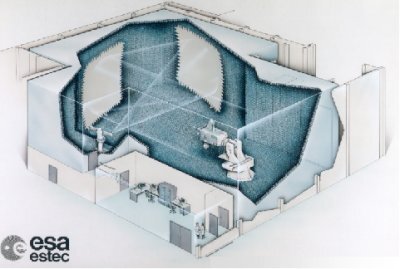
This can be performed in the ESA testing facilities, which allow high quality characterization in real installation conditions (including real antenna support and protection elements).
The GNSS equipment antenna is characterized in terms of:
- Antenna Gain Pattern (versus azimuth and elevation)
- Antenna Phase Center versus azimuth and elevation
- Out of band rejection
- Differential group delay
- Antenna Phase Centre