

Electromagnetic compatibility
It is essential to ensure that the electrical and electronic equipment within a spacecraft function correctly. When switching on an experiment for example, if other payload systems, such as the telemetry or other telecommunications links, were disturbed or even disrupted, there could be fatal consequences.
Engineers design electromagnetic compatibility verification measurements to ensure both:
- compatibility of a system to operate in a specific environment that is subject to electromagnetic interference caused by radio frequency or electrical noise from many sources
- mutual compatibility of different units operating within the same system, for example, a satellite
Another source of interference, and a very harmful one, is electrostatic discharge. Electrostatic charges accumulating on conducting or non-conducting surfaces can cause high potentials and subsequent discharges that may damage electronic circuits and lead to serious malfunctions.
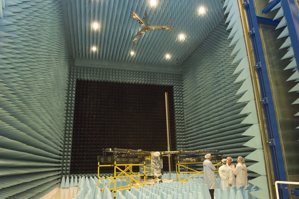
Test Chamber

The ESTEC Maxwell Test Chamber consists of a shielded enclosure, commonly called a Faraday cage, with continuously conducting metal walls, floors, and ceilings. The walls and ceiling are lined with an absorbent, anechoic material designed to attenuate the reflected electromagnetic energy. The floor is lined with ferrite absorbers and mobile resistive absorbers. The wall opposite the main door is lined with air-cooled high-power resistive absorbers capable of dissipating up to 3 Watts per square centimetre. Ceiling and floor absorbers are specially coated to prevent particle release so as to preserve the class 100 000 cleanliness level.
There are two more Faraday cages attached to the facility. The Electromagnetic Compatibility (EMC) test instruments are operated from one, and the unit or system being tested from the other.
The design of the facility, based on 30 years of experience, incorporates a number of unique characteristics that ensure that tests are carried out in the most effective and economical way possible. These include the use of fibre optics for communications and for susceptibility monitoring.
The test sequences are fully automated and are conducted in both the frequency and the time domains. A dedicated data acquisition system controls each step of a test programme thus providing maximum security to the test specimen. Engineers separately plot test data, collected through antennae, current, and voltage probes, with a clear identification between narrow-band signals and broadband coherent and incoherent noise.
The facility is particularly well adapted to carry out electrostatic discharge tests on spacecraft and to verify the effects of the discharges on the test specimen. The system, which has an overall dynamic range of 160 decibels, includes active sensors for measurements of the magnetic and electric fields and of the surface current.
Continue reading below
Emission and susceptibility testing
All emission tests in the frequency and time domain are fully automated. Tests are computer-controlled with online data reduction, narrow, and broadband identification and corrections for probes factor.
Output data are stored and plotted. A printout is available of all values measured in numeric order together with the levels compared with the relevant specification.
Time domain measurements are also an integrated part of the test activities. A bus-controlled oscilloscope is used for this purpose.
Susceptibility testing is also fully automated. This avoids the problems of manual operation where the operator has to control the frequency with one hand, the amplitude with the other, and, at the same time, check the modulation, the overload of the amplifiers, and so on. All these control and check functions are handled by a computerised system. This provides an accurate and fully corrected measurement, calibrated on the spot at each frequency step. Above all, the system can make the measurements any number of times without the slightest deviation.
Engineers can carry out both electrostatic discharge and susceptibility tests on large ground stations or computers to detect bonding faults and ground loops. This can considerably cut back on expensive facility time.
For more information please contact Gaetan Piret, ESTEC Test Centre Manager.
Gaetan.Piret @ esa.int