Optical signal advances
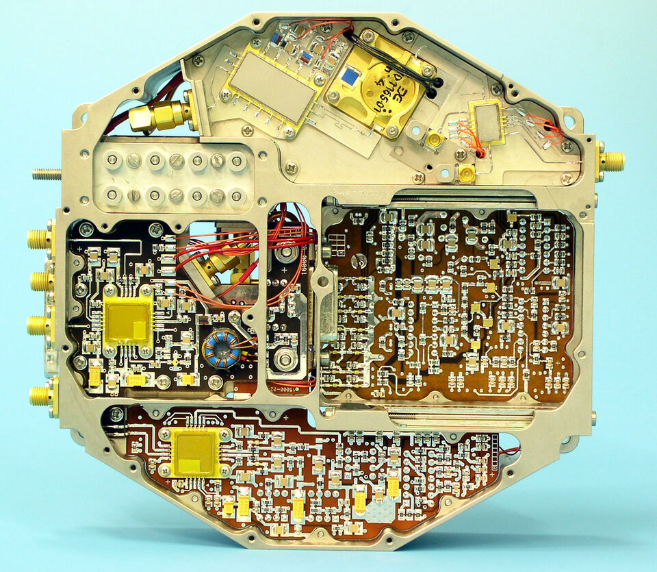
A third major challenge was to relay the electrical signals from the receivers to the correlator without contaminating the measurements. Dr Martin-Neira adds, “MIRAS is basically a receiver, detecting very faint thermal noise from Earth’s surface, which has to be amplified ten billion fold before it is used. Any electrical noise leaking out from the electronic box or arms can influence correlations and blur the resulting images.
"To overcome this, from the very beginning we proposed that optical fibres would link all the signal receivers with the correlator unit. Optical fibres relay information with light pulses rather than electrical signals, so they do not produce any electromagnetic radiation. This was a brave approach because ESA had never flown an optical harness in space. In fact, MIRAS will be our first.
“You can imagine the enormous difficulties involved if we had gone with an electrical harness and then, when the instrument was completed, found that somewhere inside it a signal was polluting the results. At that stage it would have been an insurmountable problem.”
But before such an optical harness could be built, the MIRAS team had to build expertise in this novel field. That meant carefully grading optical components available in the commercial market, gaining insight into their manufacturing methods and performing specialist testing to assess their suitability for the space environment.
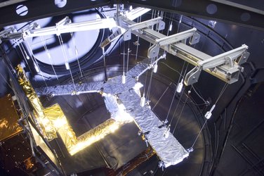
The decision to employ optical fibres also turned out to be beneficial in other ways. MIRAS will fly to orbit aboard SMOS with its arms folded down, then deployed in orbit. The mission is designed right to the edge of the mass and power consumption limits dictated by its French-made Proteus satellite platform. However, optical fibres weigh less than electrical wires, so the arms need less force to unfold, meaning that simpler spring-loaded motors can do the job instead of heavier electricalversions, cutting both instrument mass and power requirements.
Demonstrator dictating a fresh equation
The 2002–03 MIRAS airborne demonstrator was basically a cut-down version of the final instrument, with four receivers each on its three arms plus a central receiver. Reflecting its astronomical heritage, test images of the Sunand Moon against the empty sky were made first before the start of land and sea scanning. The instrument’s completion also provided a welcome opportunity to bolster its theoretical underpinning.
“When we were making end-to-end measurements for the first time we realised something important,” says Dr Martin-Neira. “The standard equation that astronomers use for radio astronomy was no longer applicable. They use big antennas separated by large distances while with MIRAS we have many small antennas clustered at very small distances. We basically rewrote the equation to describe this operation. In the process, we turned out to build a scientifically useful bridge between radio astronomy and microwave theory that did not exist before the engineering model was completed.”
This new formula, named the Corbella equation, also guided the MIRAS team towards a reliable method of calibrating the instrument and checking for errors, telling them it could be done by looking at some uniform reference, such as the uniform cosmic background radiation of deep space. So once in orbit, SMOS will be regularly flipped to look up at the ‘cold sky’.