Phantom antenna
The MIRAS concept involves detecting faint microwave energy radiated from Earth’s land and sea surface in the L-band range (a classification derived from Second World War radar), more typically employed by radio astronomy to observe deep space.
“MIRAS is really a radio telescope looking down instead of up,” adds Dr Martin-Neira. “But to gather an image of useful resolution would require a classical antenna of at least eight metres across – far too bulky to fly on the launcher and satellite platform available.”
Instead, MIRAS borrows from radio astronomy again, using a technique called ‘aperture synthesis’. This involves the precise combination of radio signals from multiple antennas a fixed distance apart. This process produces an image resolution equivalent to a kind of ‘phantom’ single antenna, its diameter equivalent to the maximum ‘baseline’ distance between antennas.
Radiometer receivers need to ‘see’ as one
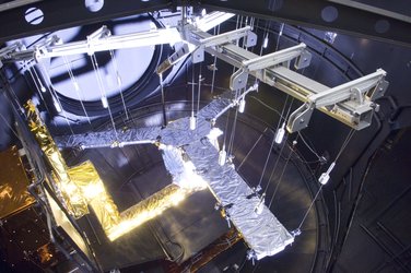
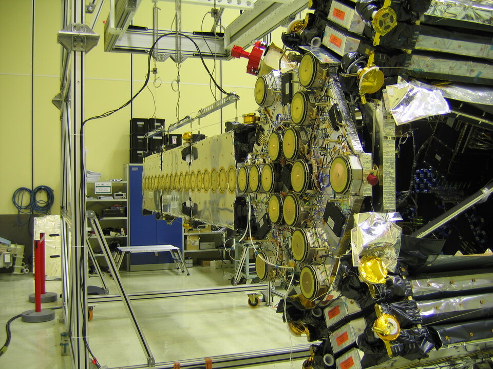
“This technique requires the clustering of many small receivers along the three arms of MIRAS,” says Dr Martin-Neira, “radio astronomers having advised that a Y-shaped array is the single most effective sampling shape. This was a completely new concept, and presented the first problem we faced. The 69 receivers MIRAS requires had to be lightweight, consume low power and be extremely similar to each other in electrical terms if the instrument was going to work as planned.
“The approach we took was that all receiver components would have a wider bandwidth than the nominal one, but similarity of response would be imposed by a single element: a ‘passband filter’. Only this filter had to be made identically. That involved a combination of metals to build it, and mechanical and electrical design such that all filters had the same frequency response that did not change with temperature. And even if there was a little bit of movement, all the filters would move in the same way."
The MIRAS arms were built from rigid carbon fibre reinforced plastic to prevent mechanical deformation from the violent temperature shifts experienced in orbit. The receivers need to remain fixed distances apart for the instrument to function – with a tolerance of about 1 mm across each four-metre arm length.
Temperature shifts can also cause changes in electrical response, so the arms have an active thermal control system to keep all the receivers within ±3°C of each other. This threshold is enough to guarantee instrument performance, with internal software providing additional correction as measurements are made.
Into a new dimension
“Beyond the need for identical receiving elements, our second challenge was the vast amount of onboard ‘interferometric’ processing required,” says Dr Martin-Neira. ”MIRAS builds up an image by multiplying together the signals received by all possible pairs of receivers.”
‘One-dimensional radiometer aperture synthesis’ had already been achieved in a US airborne sensor using a very small number of receivers to build an across-track image. What made MIRAS so ambitious in the 1990s was the idea of breaking through from one- to two-dimensional imaging. It meant squaring the total number of signal multiplications performed – all of which had be performed aboard the satellite because the data rate to the ground would have been prohibitively large.
“Several thousand multiplications must be performed in something like 20 nanoseconds,” says Dr Martin-Neira. “Back in the early 1990s, it was not obvious how this was to be done, but in the end ‘Application Specific Integrated Circuits’ (ASICs) were designed and built specifically to perform these calculations.” ASICs are computer circuits that are custom-designed for a particular task. Nine ASICs are placed in a central electronic unit of MIRAS, known as the correlator.