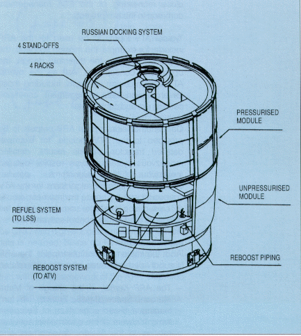
Figure 1. The ATV (Phase-B configuration)

ESA's contribution to the International Space Station (ISS) was decided in October 1995 by the ESA Council meeting at Ministerial Level in Toulouse (F). One of the main elements of that contribution is the development of the Automated Transport Vehicle (Fig. 1), an unmanned, Ariane-5-launched vehicle that will perform regular reboost/refuelling and payload supply/removal missions to the ISS.
Figure 1. The ATV (Phase-B configuration)
More specifically, the ATV's primary role will include:
Clearly, therefore, complete mastery of auto-mated rendezvous technologies is an absolute must if the ATV is to be capable of fulfilling these highly demanding mission objectives. Three essential benefits of the Automated Rendezvous Pre-development (ARP) project to the ATV's development proper are therefore:
It will also be possible to reuse the ARP results in other future ESA projects calling for automated rendezvous capabilities.
The development, verification and validation of the ATV's automated rendezvous capability will be a progressive process of verification and validation based on the three main stages of the ARP Project (Fig.2)

The ARP outputs intended to be used directly or indirectly in the ATV's development are:
It is crucial to maintain the tightest possible interfacing between the ATV and ARP projects, in order to:
In practice, ATV/ARP coherence is ensured via joint reviews and phased milestones, under the close monitoring of the ESA management common to the two projects.
Typical ATV inputs to be used for the ARP include, for example, the mission scenario, the approach strategy, the trajectory design, the operations concept, as well as the overall ATV system-design concepts, including those for propulsion, data management, communi-cations, ground control, etc.
On the other side, typical ARP outputs to be provided to the ATV include, for example, detailed trajectory-analysis results, detailed rendezvous system-analysis results, detailed rendezvous- related algorithms, detailed environment-modelling algorithms for the ATV spacecraft and the space environment, results of closed- loop real-time simulations of the prototype rendezvous control software, etc.
From the implementation standpoint, the ARP is subdivided into three strongly inter-related contracts:
This distribution of responsibilities not only meets ESA's geographical-return constraints, but also ensures the widest possible dissemination of the resulting knowhow within the space industries of the participating ESA Member States.
The three flight demonstrations (discussed below in more detail) are based on flight opportunities offered by NASA as one of the major elements of the overall Inter-Agency ISS Cooperation Agreements. In addition, dedicated agreements have been reached between ESA and the German National Space Agency (DARA) for the utilisation by ARP of the Orfeus-Spas satellite (FD1) and of the MOMSNAV experiment (FD2 and FD3). Finally the Russian part of FD2 and FD3 has been implemented by means of a commercial agreement with the RSC Energia company. ESA is directly responsible for the technical management of these components of the ARP project, and as a result ESA's role within ARP is not limited to the 'institutional' function of customer, but it is rather that of a 'Super-Prime Contractor'. This adds another element of interest to the ARP project from the management standpoint.
Part 1 of the ARP activities (pre-developments for the 'long- range' rendezvous leg), initiated in mid-1994, will be completed by summer 1997. The first ground simulation campaign within this slice of the project (GPS open-loop) was performed during the summer of 1996. Part 2 of the work (the 'short-range' rendezvous leg) was started in the spring of 1996 and will continue until the first half of 1998.
The prototype of the ATV RV Control System being elaborated within the ARP Kernel consists of:
plus a Communication Simulator allowing the GOAS to interface with the onboard components of the RVC System.
The resulting RVC System prototype will be capable of real- time running. The ATV onboard part will be implemented on an ATV- like processor, and it will be connected to hardware models of the RV Sensor and of the GPS Receiver.
Then the ARP Kernel activities include the design, development and validation of the RV verification facility (RVGS), to be used first within the ARP itself and then provided to the ATV as a validated framework for further RV verification test campaigns. The RVGS will be based on the simulation environment provided by Eurosim (ESA's real-time simulation software platform), and it will comprise the following elements:
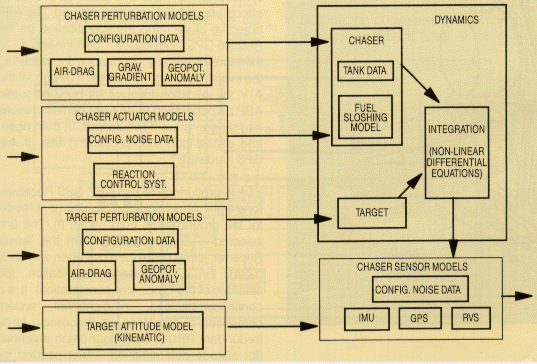
Figure 3. RVGS software model architecture
For system-verification purposes, the RVGS is also used with real hardware in-the-loop (RVS and GPS Receiver), in conjunction with the following additional verification facilities:
The ARP Kernel design and development tasks will then be completed by a large number of ground simulation campaigns in combination with the three flight demonstrations mentioned earlier.
For the last portion of the automated rendezvous manoeuvre, from a range of few hundred metres until physical contact between the docking systems of the ATV and the ISS Service Module, a sensor capable of providing the GNC with high-accuracy relative navigation data is needed. Since no RV Sensor with the required characteristics was available, ESA decided to undertake development of this key item within the framework of the ARP.
The ARP RVS is being developed by DASA Jena Optronics, using an earlier technology development by DASA/MBB as a starting point. It works according to the following basic principles:
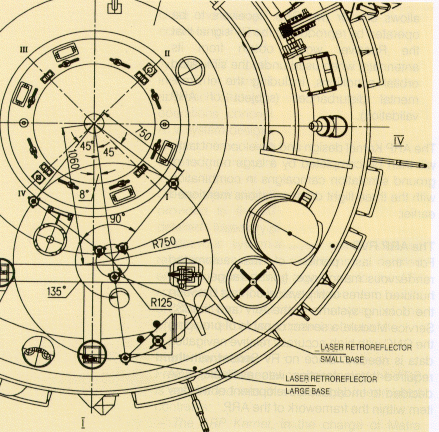
Figure 4. RVS target pattern on the ISS Service Module
The RVS consists physically of two separate units, the Sensor Head (sketched in Fig. 5) and an Electronics Unit. Two models of the ARP RVS will be delivered: a development model for the ground simulations and a protoflight model for the flight demonstrations.
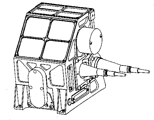
Figure 5. The ARP RV sensor head
Because of its working principle, RVS performance could be sensitive to parasitic illumination effects as well as the relative motions of the two vehicles. Given that the safety of both the chaser vehicle and the target vehicle and its crew is critically dependent on the RVS working correctly throughout the approach, its validation represents a major contribution to the validation of the ATV's complete automated RV System. Two flight demonstrations and several ground simulations in a realistic environment, in both open-and closed-loop modes, are therefore planned, all of which will make use of real RVS hardware.
Relative navigation using GPS receivers has not yet been applied operationally in any space project, although several features of the 'long-range' leg of the ATV RV System rely heavily on the expected performance of this method of navigation.
One major unknown is the multi-path effect, but synchronisation-error and selective-availability effects are also not yet well-mastered. The ARP objective of securing the specification on the Relative-GPS navigation performances is therefore of primary importance for validating the overall automated RV System design for the ATV. Its validation also will be pursued within ARP by performing three flight demonstrations and several ground simulations, in both open-and closed-loop modes, making use of real GPS hardware.
ESA is procuring the two ARP GPS Receivers (one flight model and one development model for the ground tests) from Laben (I). The unit selected is derived directly from the Tensor Receiver, jointly developed by Laben and Loral (USA) for a commercial application (56 satellites of the Globalstar constellation). It is a continuous-tracking, nine-channel system composed of two Receiver Processing Units (redundant RPUs), up to four patch antennas (for attitude determination - not needed for ARP), and up to four pre-amplifiers (in a stack). In particular, each RPU weighs 1.8 kg and comprises an RF section, a digital section (based on a C-MOS ASIC for signal processing and a RAD-6000 micro-processor), and a DC power-supply section. The external data interface is via RS 422.
The ARP GPS software has been modified to allow direct output of the so-called 'raw data' (pseudo-range, carrier cycle count, pseudo-range rate), which are then processed by the R-GPS navigation algorithms predeveloped by the ARP Kernel. The overall architecture of the ARP GPS is shown schematically in Figure 6.
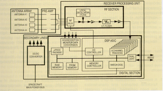
Figure 6. ARP GPS architecture
The ultimate objective of ARP is to validate a number of items which will then represent the basis for the automated rendezvous of the ATV, where validation means 'proving that a given item behaves as expected when exercised in the real environment'. Such complex validation objectives can be subdivided into three main groups:
Validation of RV concepts, specific equipment and
related models
Proper validation of R-GPS and RVS-
based navigation technical elements is essential, due to their
novelty. They include RVS performance validation, RVS navigation-
concept validation as well as RVS equipment (and measurement
environment) modelling for the 'short-range' RV leg, and GPS
receive performance validation, R-GPS navigation-concept
validation as well as GPS measurement-system modelling for the
'long-range' RV leg.
The ARP Flight Demonstrations will be the essential contributors to these validation steps.
Validation of other models
This group
includes the validation of software models necessary for
representing the 'external world' for the RVC system. They
consist of:
for which a validation process needs to be established, including comparison and parallel activities with NASA (see later) and, when possible, use of Flight Demonstration outputs. Full validation of the items in this group will only be possible within the ATV framework.
Validation of tools and facilities
This
group includes the part of the RVGS residing in the Eurosim
facility, as well as the other system verification facilities
(i.e. Eurosim connected respectively to EPOS and GPS Lab.). The
ARP validation activities are expected to demonstrate their
suitability for later use by the ATV. In particular, they should
provide the necessary that the software models included in this
group do indeed provide a correct representation of the RVC
external environment when they are connected together.
Cooperation with NASA
Substantial
benefits in the model-validation domain are expected from
cooperative activities with NASA. In practice, it is envisaged
to perform: (a) documentation exchange and comparison analysis
at 'equation level', and (b) parallel open-loop simulation runs
of respective model algorithms on similar input files. The basic
objective of this work is to establish confidence in, or at least
assess, the representativeness of the physical behaviours being
modelled. The global logic of such activities is represented in
Figure 7.
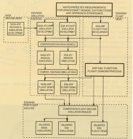
Figure 7. ESA/NASA model-validation logic
The only ground simulation campaign so far completed is the GPS Open-Loop Test Campaign, conducted by the ARP Kernel Prime Contractor (MMS) at the ESTEC GPS Laboratory, with the support of the ARP GPS Contractor (Laben). The specific objectives of this campaign were:
Four series of tests representing various mission profiles - no movement, circular orbit, ATV orbit and ISS orbit for a V-bar approach - have been run, with the following preliminary results:
Flight Demonstration 1
ARP Flight Demonstration 1 (Fig. 8), a Relative-GPS
experiment, was performed during a Space Shuttle flight (STS-80)
between 19 November and 4 December 1996. The NASA vehicle
deployed DARA's Orfeus-Spas satellite, which carried the ARP GPS
Receiver. A second GPS Receiver, supplied by NASA, was mounted
on the Shuttle. The latter also carried a NASA-supplied optical
sensor to track a retro-reflector mounted on Orfeus-Spas, in
order to acquire 'true' data in parallel with the R-GPS measurements.
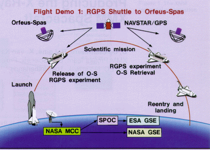
Figure 8.Overview of Flight Demonstration 1
The experiment was performed during both the deployment and retrieval of Orfeus-Spas by the Shuttle. During these periods of about 45 min and 8 h, respectively, the two spacecraft were oriented so as to allow simultaneous zenith-pointing of the antennas of both GPS Receivers. The GPS measurements (raw data) gathered during the experiment were recorded for offline post- processing, which is about to commence at the time of writing.
In addition, data output from the GPS System satellites (Navstar) during the flight demonstration were recorded by ground-based stations equipped with GPS receivers (task coordinated by ESOC), to get the support of differential-GPS techniques for the determination of Best Estimated Absolute Trajectort (BEAT) and Best Estimated Relative Trajectory (BERT).
Flight Demonstrations 2 and 3
Flight Demonstration
2 (FD2) consists of a Relative-GPS and an optical Rendezvous
Sensor experiment, to be performed during Shuttle flight STS-84,
scheduled for launch on 15 May 1997. During this mission, the
Shuttle will rendezvous and dock with the Russian station Mir.
The ARP GPS Receiver will be installed on the Shuttle, while the
second set of GPS Receiver measurements will be delivered by
DARA's MOMSNAV experiment already installed in Mir's Priroda
module. The ARP RVS will also be installed on Shuttle; its target
pattern will consist of three retro-reflectors already mounted
on the Mir Docking Module. Similar to FD1, 'true' data will be
available from the NASA TCS aboard the Shuttle.
This experiment will also be performed during both the Shuttle's approach to and departure from Mir. The GPS and RVS measurements gathered will again be stored onboard for later post-processing (Fig. 9).
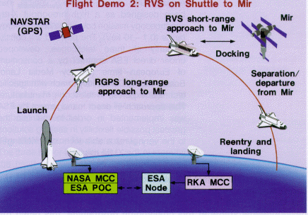
Figure 9.Overview of Flight Demonstration 2
ARP Flight Demonstration 3 (FD3) will be a reflight of FD2 on Shuttle flight STS-86, scheduled for launch on 18 September 1997. It will represent the ideal opportunity to refine and improve the learning obtained from FD2, to fine-tune the experiment if required, and to correct for any unforeseen occurrences during the earlier flight.
From the R-GPS validation standpoint, FD2 and FD3 will represent a step forward with respect to FD1 because they will not take place in the near-ideal, unobstructed Shuttle/ Orfeus- Spas environment, but in a scenario much more representative of the real ATV/ISS rendezvous, thereby generating more valuable information with respect to multi-path effects, shadowing, etc.
The ESA Automated Rendezvous Pre- development (ARP) project is designed to help European Industry master the automated rendezvous and docking technologies that are crucial to the success of the ATV missions to the International Space Station. It will generate important products to be used in the ATV's final development, including the prototype Rendez-vous Control System, the Rendezvous Ground Simulator and the Rendezvous Sensor, and will validate them by means of three flight demonstrations and several ground simulation campaigns.
In addition to its direct exploitation of these ARP products, the ATV project will also benefit from the specialised knowhow accumulated by the various industrial teams throughout Europe involved in the ARP.
The planned Protoflight Mission to conclude the ATV development and verification process will serve as the final demonstration of the ATV's ability to perform automated rendezvous and docking with the ISS Service Module.
The authors would like to acknowledge contributions from colleagues involved in the ARP activities, in particular U. Thomas, W. Fehse and D. Paris (ESA), G. Limouzin and D. Thomas (Matra Marconi Space), K.H. Kolk and B. Möbius (DJO), and G. Adami (Laben).


 ESA Bulletin Nr. 89.