
Deployment Mechanism for Solar Concentrators
| 635 - Abstract: |
| ESA has developed a method for deploying solar concentrators that fits within the standard frame of the solar panels. This system enables more light to be captured per area of solar panel thus improving the performance whilst reducing cost and weight. This deployment mechanism has applications both within space and back on Earth. ESA is looking for partners who would be interested in licensing and implementing this design. |
Description:
Solar panels for space applications are very expensive and many methods and technologies have been employed in an attempt to improve their efficiency by increasing the amount of light gathered by a given number of cells. One of these technologies is solar cell concentrators – essentially foil panels either side of the solar panel that are angled such that they focus more incident light onto the photovoltaic cell. However, the majority of these have significant drawbacks when used in space either in terms of performance, cost, or lifetime.
ESA has developed a deployment and locking mechanism that fits within the frame surrounding a standard solar panel. It overcomes the performance issues caused by shrinkage which is common in the standard systems that depend on tethers to maintain alignment.

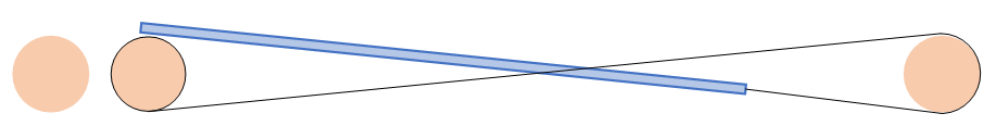
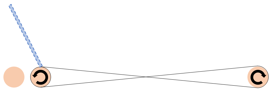
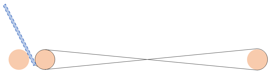
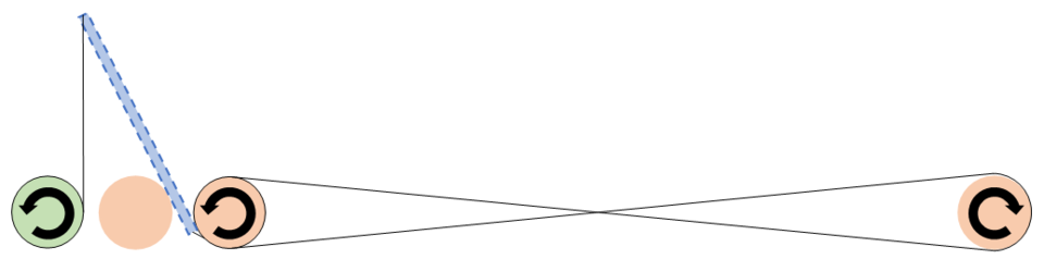
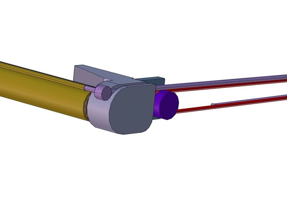
The mechanism is designed around the concept of deploying a solid strut using counter rotating cylinders joined by a cable. The strut is attached to a cable which is then wound around two cylinders in a figure of eight manner. When the central cylinder rotates anti-clockwise it induces a clockwise motion in the right-hand cylinder which in turn allows the strut to move out. Once the strut reaches the end of its travel it then becomes lodged between the left and centre cylinders. (the strut with the dashed edge has only been shortened for drawing clarity – in the actual system it remains the same length.
Figures 1-4 below show the deployment:

For added rigidity in systems and structures that require it, tethers can be attached to the far end of the strut from additional cylinders (see Figure 5).
The mechanism is replicated on the opposite ends of the cylinders and a reflective foil is spread between the two struts. Prior to deployment this is wrapped around the centre (orange) cylinder. Depending on the exact application an appropriate insulation layer can be added as a backing to the foil. This prevents warping of the foil due to the temperature differential between the two sides.
Innovations and advantages:
- Reduced overall system cost
- More power per solar panel
- Reduced weight
- Reduces dependency on tethers that can contract/expand
- Fits within frame of standard solar panel
- Can easily accommodate different thermal insulation layers
- The manner in which the strut finishes its journey result in low latching shocks.
Domain of application:
- Telecommunications Satellites
- Large arrays of solar panels could be supplemented or partially substituted
- Small sats/cube sats
- Improve energy harvest whilst maintaining low weight and cost
- Terrestrial Applications
- Compact, deployable structures for advertising/exhibition stands