


 Germany
 Austria
 Belgium
 Denmark
 Spain
Spain
 Estonia
 Finland
 France
 Greece
 Hungary
 Ireland
 Italy
Italy
 Luxembourg
 Norway
 The Netherlands
 Poland
 Portugal
 Czechia
 Romania
 United Kingdom
 Slovenia
 Sweden
 Switzerland


Software Tool Predicting the Distance Measurement Equipment (DME) Interference Environment for Galileo
| Programme: | GSTP | Achieved TRL: | n/a |
| Reference: | G609-77ET | Closure: | 2016 |
| Contractor(s): | DLR (DE) | ||
While the European satellite navigation system GALILEO was being planned, the prospects for new services became increasingly favourable. Therefore, new frequency bands had to be acquired for these new services. It was obvious that the E5 band was selected for aeronautical broadband services. This band had been already allocated by ITU for aeronautical navigation since the DME (Distance Measuring Equipments) system has been located in this frequency band. The technical nature of DME enabled an overlay with GALILEO as a secondary user since the satellite signal is much weaker than the DME signal. This allowed a very fast clearance within the World Radio Conference to use this band for GALILEO. On the other hand, the usage of DME is expected to be a strong interferer for GALILEO. The DME system radiates short but strong pulses in the E5 band. Thus, a GALILEO receiver must be equipped with an effective DME mitigation technique.
Objectives
The goal of this project was to answer these questions concerning the effect of airborne interference on GALILEO. Today many GALILEO signal generators (e.g. SPIRENT, IFEN, GSVF etc.) are available, but all of them are lacking a mature model for DME interference. Therefore, a model has been be developed capable of generating the interference signal from any DME constellation and any aircraft position and orientation respectively. To allow a user to generate the interference signal by pressing a single button, the model has been implemented in a ready to use software including an interface to hardware signal generators. This tool allows the user to simulate current and even future DME signal interference situations very precisely. The generated interference data can be directly loaded onto a programmable hardware signal generator whose output is added to the GALILEO signal generators. The development of this mature prototype minimises the risk for airborne GALILEO receivers to be exposed to an unexpected critical interference load now or in the future.
Achievements and status
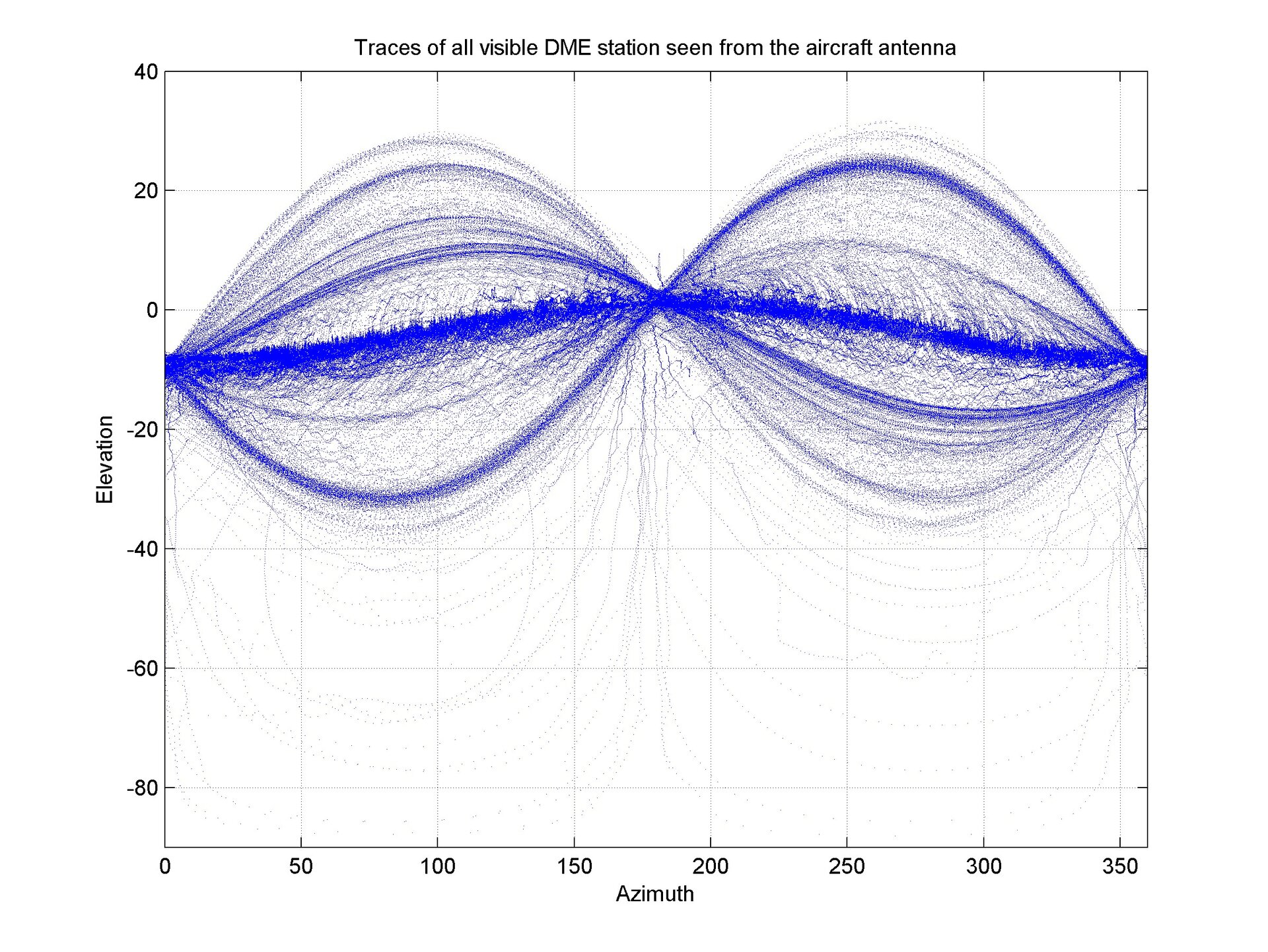
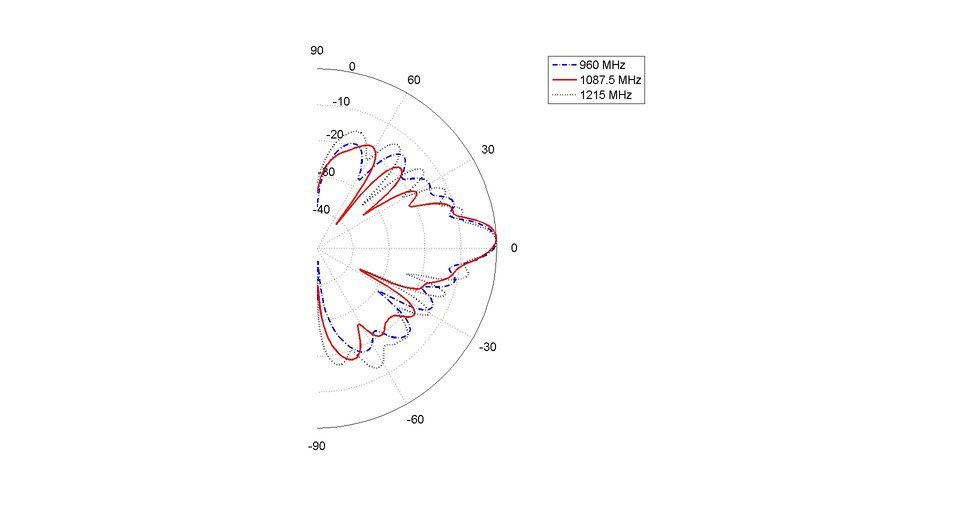
The main output of the extensive measurements is the antenna diagram representing the antenna mounted on the aircraft’s fuselage. In contrast to antenna diagrams not taking into account the fuselage, here propagation effects of the aircraft itself are taken into account. From the measurement data, we offer an antenna model based on spherical harmonic functions which can represent the antenna model by assuming a certain degree of development. At the moment the selection of this degree is not fully clarified but a range of 11…20 is recommended. Depending on the DME mode, the DME ground station is responding on a frequency with an offset of +63 or -63 MHz from the interrogation frequency. The aircraft receives this pulse and can determine the distance from the delay between interrogation and reception where the DME station introduces a known delay between reception and transmission. The interrogation signal as well as the reply signal consist of two Gaussian pulses. The distance between the pulses is dependent on the mode of the DME. The bandwidth of each DME channel is 1 MHz. While airborne interrogators use usually 300W for transmission, the DME ground station responds with up to 2kW.
For the propagation path, the only unknown is the antenna of the aircraft therefore; we define the calibration of the aircraft antenna. With this approach, about 60 million pulses found their entry into the database. In the next step, this database was unified by removing multiple entries of the same pulse in the database. In knowing the location of the transmitter as well as the position and orientation of the aircraft, it was possible to calculate the receiving direction of the signal with respect to the aircraft antenna.
Benefits
Navigation: The simulator resulting from this project is a strong tool to generate an interference signal for GALILEO. Since GALILEO is just beginning to take its first steps into the aviation world, it is an opportune time to provide a mature tool to enable receivers that are more robust, having standardised receiver tests, certification and a safe planning of the future. Our tool strengthens the competitiveness of the European aviation industry on its way to a GPS independent future.
Next steps
Anything needed to consolidate/confirm/refine the derived gain pattern of the antenna/aircraft body. This includes:
- Further analysis of antenna gain at positions below the fuselage
- Electromagnetic simulation of a patch antenna on a fuselage
- Model degree (spherical harmonics)
- A first level evaluation of worst case DME Interference at approach and en-route altitude and final step to improve interference models