
GNSS HIL Simulation Stella NGC
GSTP: Make Project: GNSS HIL Simulation StellaNGC
Company |
Country |
Website |
|
| M3SYSTEMS | France | http://m3systems.net/ | |
Today, GNSS test & measurement market is changing significantly. Major industrial domains (such as the automotive, the rail, or the aero-space) are facing new challenges for the use of GNSS. As a consequence, they are implementing new testing approaches and they requests test & measurements solutions that support them in the implementation of these the innovative testing approaches.
Although the usual GNSS simulators that generate signals based on a predefined test scenario (open loop approach) is still of high interest, there is a need in this new context to integrate the GNSS simulations into a larger test environment such as flight simulator or a car simulator which potentially users/drivers taking control in real time (closed loop approach).
The aim of the project is to upgrade M3 Systems GNSS simulator from an open loop solution to a closed loop system.
Objectives
Based on existing building-blocks from the legacy open-loop StellaNGC GNSS simulator, the goal of the project is to develop a Hardware-In-the-Loop GNSS Simulator that can support industry to implement close loop new testing modes.
This new StellaNGC will also pave the way for the integration of an IMU model so that coherent GNSS and IMU data can be generated simultaneously (e.g., for the test of GNSS/IMU data fusion solutions).
The goal is to be able to include the developed GNSS simulator into a close loop setup and thus adapt the simulation regarding the closed loop dynamic reaction.
Emphasis is put on the adoption of a layer-based design, allowing intermediate outputs and scalable system delivering.
Features
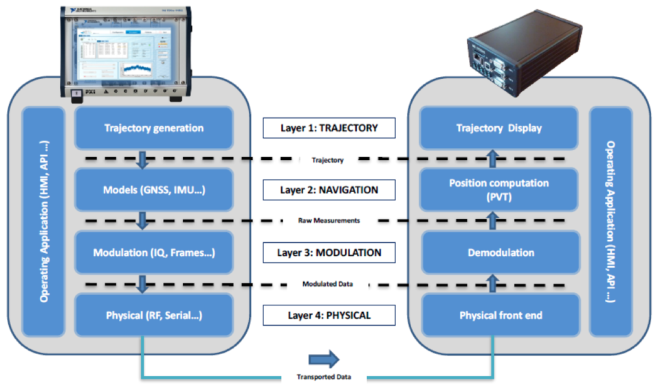
Flexibility and modularity is a key to cover the needs of the targeted markets. To ensure such versatility, M3 Systems has implemented a four layer based simulator which can therefore ‘stimulate’ the device under test with four different types of data:
- The Trajectory Layer is providing the trajectory to be simulated
- The Navigation Layer is providing the expected raw data susceptible to feed in real time an hybrid navigation filter for the simulated trajectory
- The Modulation Layer is providing a representation of the signal as recovered at the end of a receiver’s front end for the simulated trajectory, under the form of the numeric samples of the analytic signal in the baseband for the GNSS, under the form of data frames for the IMU, etc.
- The Physical Layer providing a representation of the GNSS signal as received at the antenna connector’s level, or the IMU data at the data link connector’s level, for the tested trajectory
It is worth noting that a symetric approach could be implemented on the GNSS receiver side.
Project Plan
The expected project plan is divided in four phases:
- The first phase is dedicated to the specification, the design of the system and the definition of its functional and implementation architecture
- The second phase is the development, including the sub-module integration
- The third phase is the validation of the system with regards to the specification phase
- Finally, the last phase is to perform a demonstration of the validated system
Key issues
The key issues are:
- Closed loop capability: the simulator shall be able to modify on the flight the ongoing simulation. This is a critical challenge as it highly constraints the design.
- Closed loop performance: the closed loop capability is useful if only the following performances are met.
- Response time: the simulator shall be able to get a new point and update its state with a one millisecond refresh rate
- Latency: with an input change, a user will want to have a short closed loop reaction. This latency has been defined at twenty milliseconds.
Expected Main Benefits
The two features that provide key added-value for the market are the real-time ability and the high-scalability property of a simulator.
- Real-time means that a simulator is able to answer to a new stimuli coming from its environment in “real-time”.
- High-scalability means that a simulator could be easily extendable to interoperate with the environment (e.g. CAN bus or ARINC interface, new computation capability, new software API) or to increase the capability/performances of the platform, the same platform can be used either by R&D project or validation team. Another side of scalability, it the ability of the system to perform other crucial functions. We notice that GNSS Record & Playback is part of the verification and validation process and shall be combined with the GNSS simulation to reach a high level of validation. Based on customer’s feedback, Record & Playback, on top of GNSS simulation is a way to use the same solution for the whole validation process (from R&D to production). So this ensures cost effective use of hardware platforms.
Current Status
The first phase of specification and system design has been completed and has been reviewed during the CDR.
The second phase of development is ongoing. As shown in the feature section, the architecture is divided in five modules:
- The trajectory module (layer 1) is finished;
- The model modules (layer 2) are being developed and we are about to have the first prototype for the GNSS.
- The Modulation (layer 3) and Physical modules (layer 4), prototypes are ready.
- Finally, the Operating Application module which is system transverse is ready for the trajectory module and GNSS model module. The first integration tests are being carried on.
In parallel of the specification and development phase, the validation test plan and procedures have been carried on. Currently, the validation procedures cover more than 90% of the specified system requirements.
Contact
| Project Manager: | Patrice Nouvel | nouvel@m3systems.eu |
|
26 rue du soleil levant 31410 Lavernose-Lacasse France |
M3Systems | |
| +33 5 62 23 10 83 | ||
| Additional Contact: | Olivier Desenfans | desenfans@m3systems.eu |
| Belgium | M3Systems Belgium | |
|
+32 (0)2 513 46 73 (Brussels) +32 (0)10 49 53 63 (Wavre) |
||
| ESA Technical Officer: | Olivier Smeyers |