


 Germany
 Austria
 Belgium
 Denmark
 Spain
Spain
 Estonia
 Finland
 France
 Greece
 Hungary
 Ireland
 Italy
Italy
 Luxembourg
 Norway
 The Netherlands
 Poland
 Portugal
 Czechia
 Romania
 United Kingdom
 Slovenia
 Sweden
 Switzerland


Flexible Storage Solutions for Human Spaceflight Activities
Future human exploration activities will require the transportation and storage of a large amount of fluid – as either a liquid or a gas – to support life and onboard propulsion systems. These fluids can either be transported from Earth’s orbit or obtained by exploiting in-situ resources. A wide variety of tanks storage solutions are required, with different sizes and operating temperature, while also account for low temperatures and aggressive local in-situ environments.
Small Inflatable Space Tank Engineering Model
A TDE funded activity designed, developed and tested a prototype tank, known as SISTEM (Small Inflatable Space Tank Engineering Model), for the inflatable storage of gas and cryogenic liquids. Flexible storage solutions are ideal for the International Space Station and surface habitats. They are advantageous in not only providing a low mass and volume solution, but also a high compaction capability.
Several different tanks, of various volumes and applications, can be launched together saving space, and only deployed and/or inflated once in-orbit or at their final destination. The folding and unfolding process can be repeated multiple times, while still maintaining the maximum pressure capacity, and critically the safety and design requirements for human spaceflight activities.
How Does This Tank Concept Work?
This particular design uses a 13-liter cylindrical barrel with two elliptical domes on the top and bottom. The volume of the tank is increased by inflating the structure, thereby increasing its length.
Several different functional layers are required to provide fluid containment, pressure containment and insulation for specific applications. Requirements were defined for both conventional fluids as well as cryogenic fluids. The prototype design focused on laboratory demonstration of the pressure storage with conventional fluids.
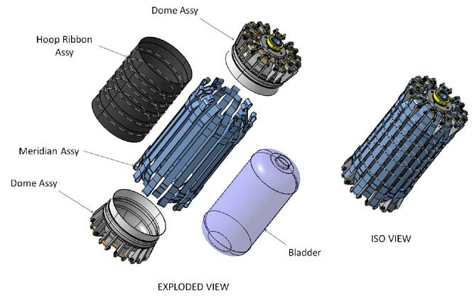
The tank assembly included:
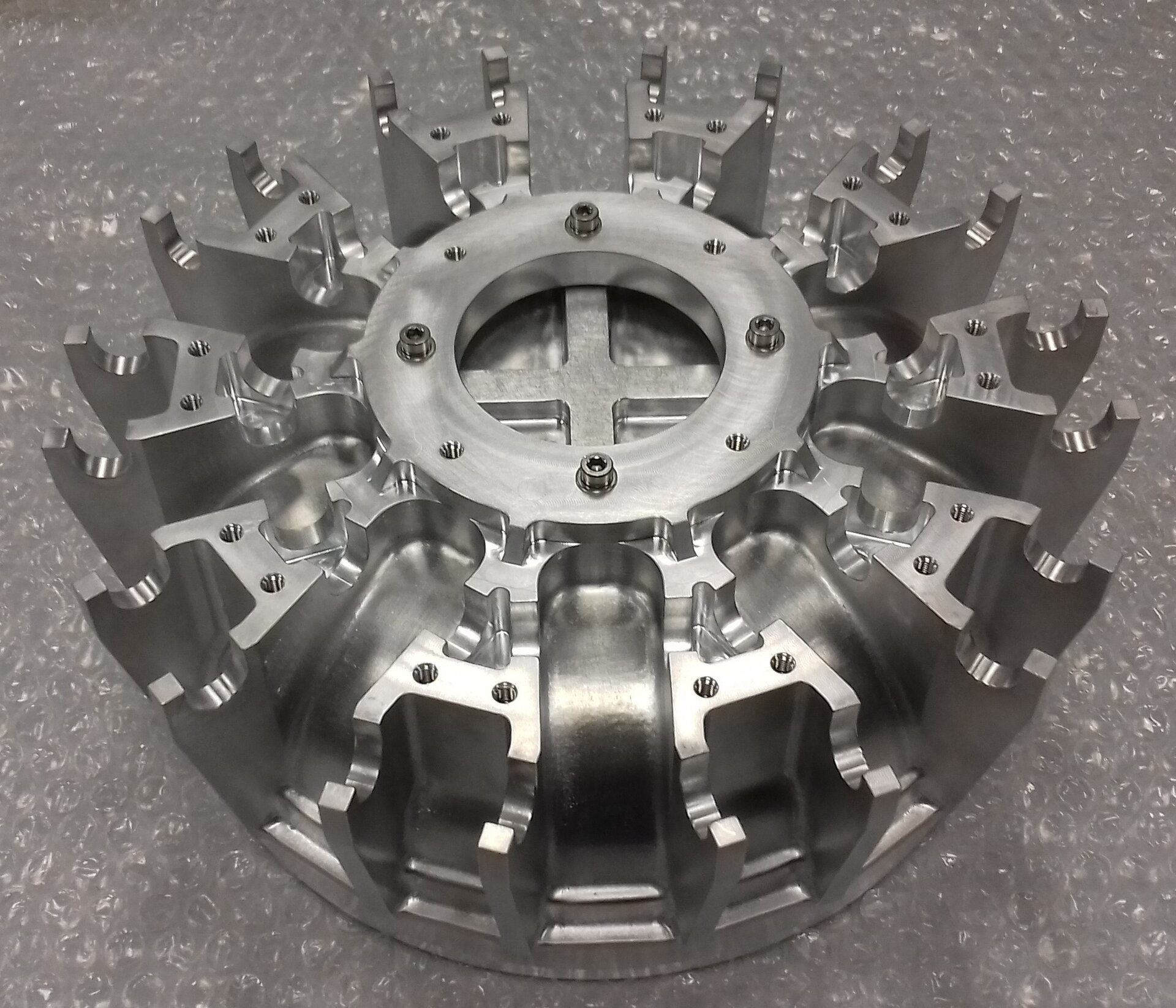
- A common dome assembly – both the top and bottom domes have the same design and interfaces, with only the fluid fitting and sealing cap being specific additions for each dome.
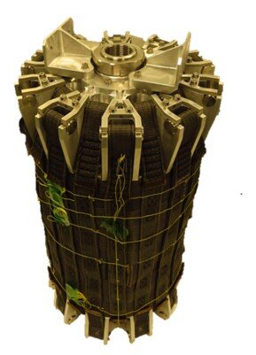
- Hoop ribbon assembly – these are the reinforcing belts that wrap around the circumference of the bladder. They support the flexible bladder to resist the pressure loads as the tank inflates.
- Meridian ribbon assembly – these are the reinforcing belts that support the tank along the length of the bladder, attaching to the top and bottom domes, and providing a load path between them.
- Bladder for fluid containment – the flexible container that holds the fluid inside the tank.
- Fluidic fitting – the inlet port to provides an interface to allow fluid to flow into and out of the tank from the external system.
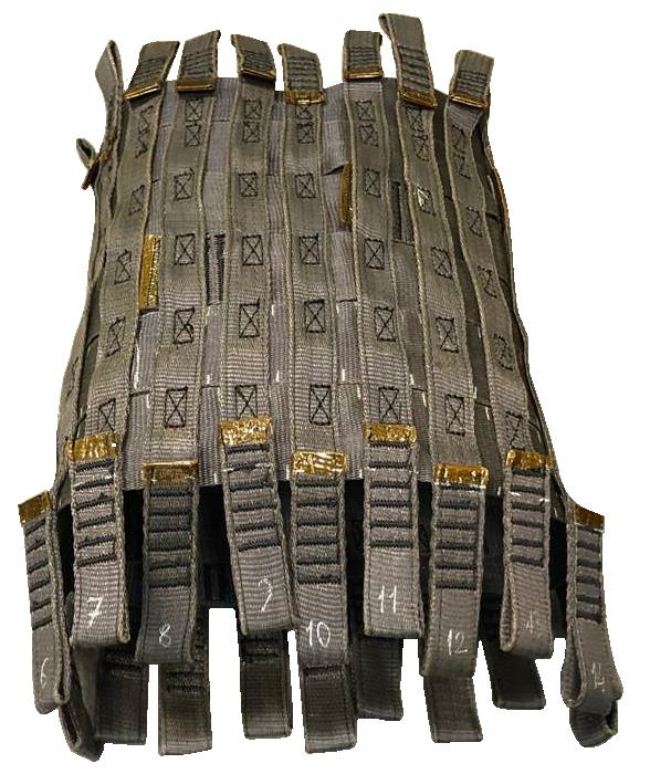
The bladder was manufactured from several pieces of Fluorinated Ethylene Propylene (FEP) monolith sheet, formed under vacuum, and induction welded together to form a cylindrical body between the two domes. The upper part of the bladder dome has a fluid interface that is already mated before finally welding the bladder together. Structural restraints are provided by a net of high-strength ribbons, manufactured from Poly-Benzyl-Oxylate (PBO) trade name ‘Zylon’. Zylon is one of the strongest types of fiber available and is coated with a VITON elastomer to protect the fiber against UV degradation. The restraint ribbons are wrapped around the tank and are sewn together at specific locations, where the meridian and hoop ribbons overlap. This provides the desired assembly joint strength and maintain tank shape in a repeatable way after many cycles of stowing and deployment.
How Was the Concept Validated?
After some preliminary design of the tank concept, the essential material properties of the flexible materials required for the restraint and the bladder were obtained in a comprehensive material test campaign. The material coupon tests covered criteria such as mechanical properties before and after ageing under UV irradiation and thermal cycling, and mechanical performance after mechanical fatigue cycling (repeated cycles of tension as well as folding/unfolding and holding under tension). The bladder material was also tested for gas permeability, outgassing and exposure to liquid nitrogen to simulate very cold conditions. Coupon tests were also conducted on samples that featured joints between materials. This assessed the strength of those joined materials before and after mechanical cycling and environmental exposure.
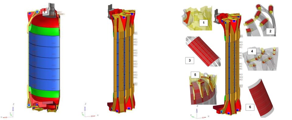
All the material data was used to improve the design of the tank demonstrator. The 13-liter tank is designed to sustain a maximum pressure of 60 bar, accounting for the maximum design pressure of 48 bar and proof factor of 1.25. A highly detailed Non-Linear Finite Element Model was built simulate the expected performance of the tank with the given materials and given design features, up to the required maximum pressure. The model accounts for material plasticity and the effects of contact between parts that will slide over one another as the tank inflates from its stowed to maximum size. Contact was defined between areas such as the domes to the bladder, the pins that hold the fabric ribbons in place and attach to the domes and the joints between the hoop and meridian belts. Symmetry conditions were used to simplify the model by analysing a segment of the tank instead of all of it.
Once manufactured, the prototype tank was subject to several laboratory tests to verify the performance and compare to the predictions.
Laboratory Testing
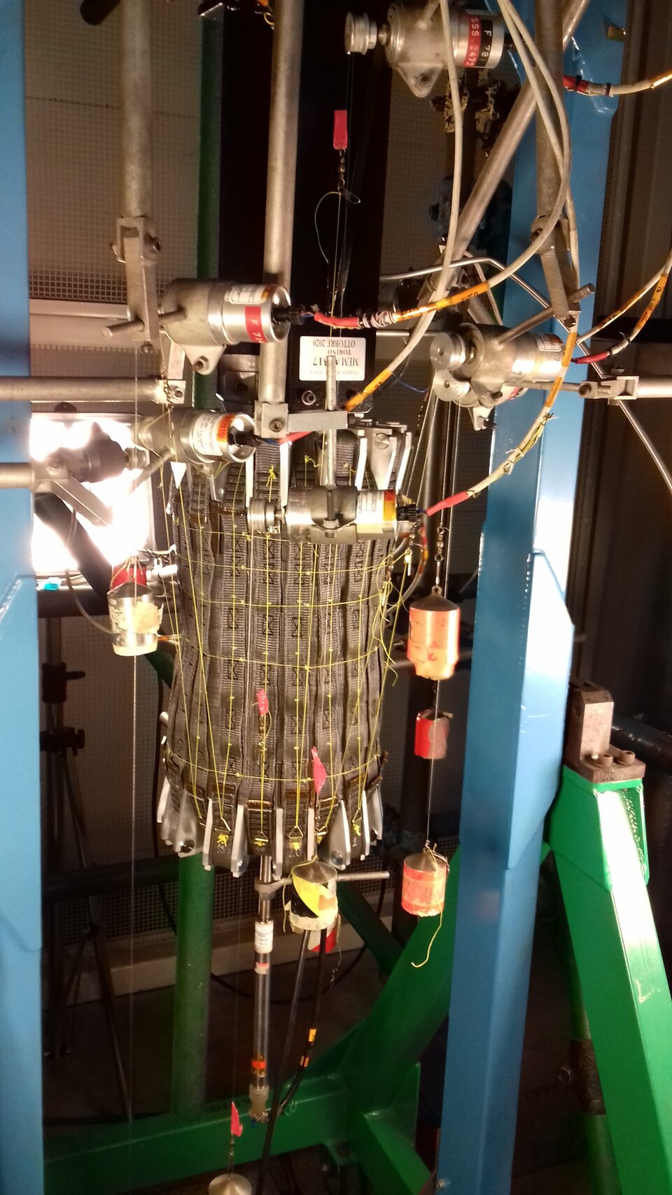
Laboratory tests successfully demonstrated the foldable system, reaching high compaction level (>60 %), and utilised 3D printed parts of the domes whilst the final breadboard parts were being manufactured in aluminum.
The tank pressure test plan was defined in several steps, as recommended in ECSS standards for pressurised hardware and fracture control. The prototype tank passed visual inspection and initial leak test, but a rupture occurred in the bladder at an area that was identified as having a manufacturing defect, preventing further pressurisation. Several attempts were made to repair the bladder and finally an alternative non representative rubber balloon was used to pressurise the tank past 10 bar pressure.
Whilst this is below the target maximum pressure of 60 bar, there was sufficient data to check the pressure and displacement of the tank against the predicted stiffness profile from the Finite Element Model. The results available from the test were within the predicted limits of strain and displacement for given pressure levels, showing the simulation was conservative and tank elongation (in the radius and along the length) were within expected values, at least for the pressure level achieved.
This level of technical assessment and prototyping is at the heart of everything that we do at ESTEC. We can establish which concepts work, or which need to be improved, before they can be applied to a specific application or service. This saves time and effort in the quest to provide mature solutions to advance ESA's goals and support an array of ESA missions, projects and activities. - Tommaso Ghidini, Head of the Mechanical Department (TEC-M)
Future Work
Further work would focus on improving the fluid containment bladder material and design to provide a more robust solution that is less sensitive to manufacturing defects.
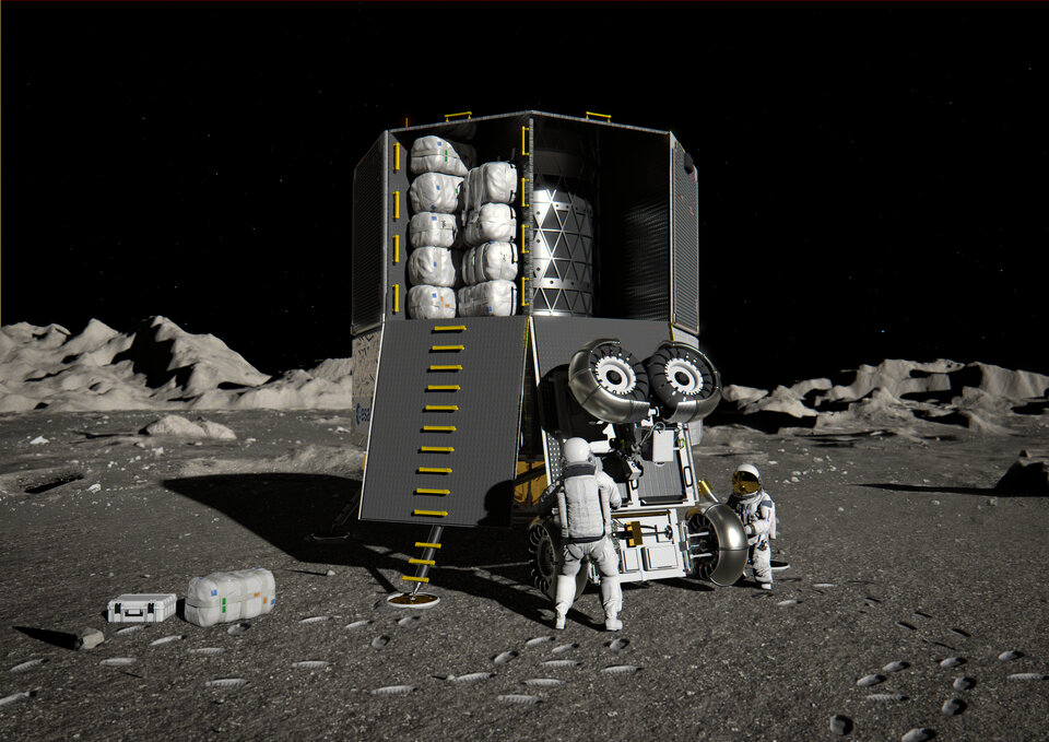
This activity adds evidence that inflatable and flexible storage solutions can bring tangible benefits to reducing mass of future exploration missions at launch, whilst adding a large volume benefit during the mission(s). ESA plans to keep studying different concepts of inflatable storage for human exploration, for example to manage resources gathered in-situ on planetary surfaces and stored under cryogenic conditions. Inflatable technology could be helpful for the ARGONAUT lander, and missions to the Moon, where storage space at launch is at a premium.
The same technology can also be applied for many Earth-bound applications, including the storage of fluids and the flexible storage of resources (oil, gas, petrol) for emergency services. The potential opportunities for technology transfer span a wide range of terrestrial and space-based applications.
The activity was led by Thales Alenia Space (Italy), together with HOLSCOT (UK), Sabelt (Italy) and Aerospace & Advanced Composites (Austria).