Shielding Solar Orbiter from the Sun
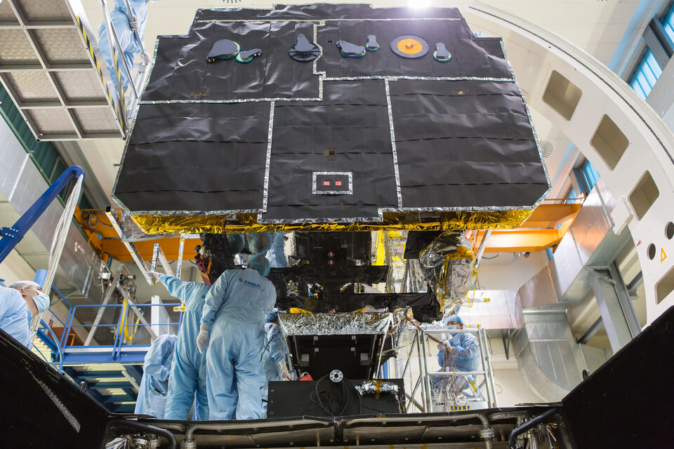
ESA’s Solar Orbiter spacecraft will venture just 42 million km from the Sun – about as close as it is possible to go and still be able to image our fiery parent star without having its instruments melt. Its cameras will peek through an advanced shield designed to dissipate heat while keeping the rest of the spacecraft within a protective cone of shadow. This heat shield took years to perfect.
ESA and Japan’s BepiColombo mission is headed into Mercury orbit, 46 million km from the Sun at its closest, but will spend half its time behind the rocky innermost planet. Solar Orbiter however, designed for close-up imaging of the solar surface, will come nearer still to the Sun – and remain in sunlight continuously throughout its projected seven-year lifetime.

NASA’s Parker Solar Probe is venturing even closer, but is sampling energetic particles, plasma and the solar wind rather than capturing images of the Sun’s surface. Its sole imager is only snapping images while looking away from the Sun, while Solar Orbiter peers directly forward – the two missions serving to complement each other.
A sky with 13 Suns
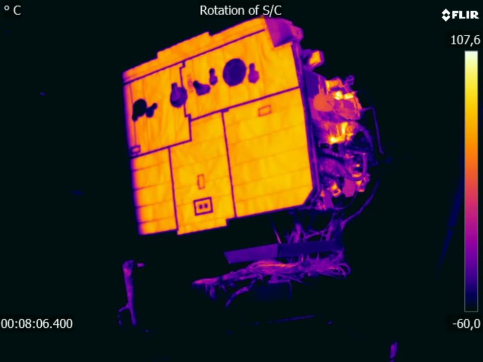
At its closest to the Sun, Solar Orbiter must withstand a solar flux of about 17 500 watts per square metre, representing sunshine 13 times more intense than experienced in Earth orbit.
So imagine having to venture out under a cloudless sky filled with 13 separate Suns, with no nightfall to break the ongoing onslaught of heat. Naturally you would want to carry a sunshade – and Solar Orbiter’s thermal designers adopted just the same strategy.
“Solar Orbiter has been able to take shape as a largely ‘normal’ spacecraft, only because it can take shelter behind an extremely powerful multi-layered heat shield, designed by Thales Alenia Space in Italy,” explains thermal engineer Claudio Damasio. He is part of ESA’s Directorate of Technology, Engineering and Quality – which serves as the Agency’s R&D department, collaborating with the Solar Orbiter team to make the ambitious mission ready to fly.

Safely in shadow
“The majority of the spacecraft will remain in the shade of the heat shield throughout its mission, except the high gain antenna, trio of Radio and Plasma Waves instrument booms and solar arrays, which of course have to project beyond the heatshield to do their work, and require their own thermal protection accordingly.”
Conceptually the 3.1 m by 2.4 m heat shield remained true to the initial design worked out when development started back in 2007: a thin surface layer of titanium foil just 0.05 mm thick – around the width of a human hair – is backed up by 18 layers of specially tailored titanium multi-layer insulation.
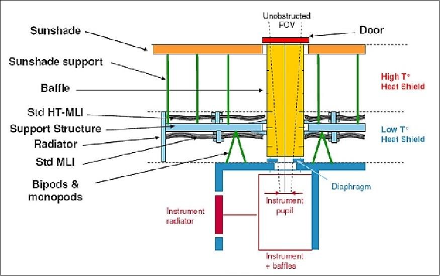
This surface layer is linked by titanium brackets across a 24.5 cm gap to an aluminium honeycomb support panel covered with high thermal conductivity carbon fibre skins and insulated by another 28 multi-layer insulation layers made of more standard space materials – comparable to the ‘space blankets’ used to keep runners warm after marathons – but still able to withstand 300 °C. The support panel is attached to the spacecraft by narrow titanium blades across a second 10 cm gap.
These multiple layers plus double gaps and thin supports are key to letting the majority of absorbed heat radiate out sideways into cold space, so that of the 110 000 watts of solar flux received by the front area of the shield, just six watts makes it to warm the main spacecraft structure.

Surface hot zone
The very front surface of the shield is also vital to its functioning. It absorbs all wavelengths of solar energy it receives, converting it into a narrower range of infrared to be radiated back out to space as heat. As an added complication the surface needs to be electrically conductive, to prevent potentially disastrous static charging building up from ongoing exposure to the solar wind.
“Ideally we wanted a white coating for the heatshield, but we couldn’t make it work in testing,” adds Claudio. “We couldn’t find any coating that the extreme ultraviolet radiation of the Sun would not degrade and shed material, risking damage to delicate instruments. We then shifted to black.
“To compensate for thermo-elastic dilatations due to temperature shifts from 20 °C at launch to more than 500 °C in flight, the shield was designed to be highly flexible. That gave us the problem that paint would not adhere to the shield, while attaching mirror-like optical solar reflectors proved impossible because we had no glue that remained reliable at high temperatures.
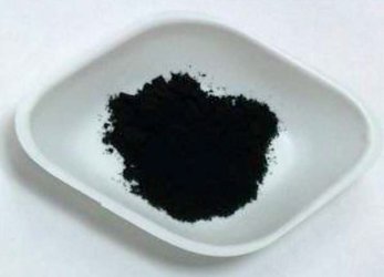
“We were on the verge of adopting bare titanium, but that would have resulted in a temperature of 700 °C at the front of the heatshield, and required many more layers of multi-layer insulation to compensate, adding to its overall mass. That was when we adopted Solar Black from Irish company Enbio, using a treatment originally developed for medical implants to chemically bond black calcium phosphate to the metal. Effectively it becomes part of the metal, so it never comes off.
“For us, this effectively saved the project. It meant the surface would retain constant ‘thermo-optical properties’ – maintain the same black colour despite years of exposure to extreme ultraviolet radiation – so we keep thermal stability throughout the mission, setting maximum surface temperature at 520°C and no more.”
Peering Sunward
Solar Orbiter’s instruments look through the heatshield via a set of eight ‘feedthrough lines’ topped with hinged protective covers. “Each instrument has its own thermal protection built in, to prevent them being overwhelmed by heat,” adds Claudio.
“These are the equivalent of wearing sunglasses – polarised glass and mirrors to block some of the sunlight. And in the event any of the instruments fail, their feedthrough cover can be closed to protect the rest of the spacecraft.”

Continuously illuminated by definition, Solar Orbiter’s solar arrays have their photovoltaic cells interspersed with optical solar reflectors to keep down their surface temperature. The arrays will also be inclined at steep angles to the Sun to control their heating.
Similarly, the mission’s high gain antenna – the spacecraft’s main communications link back to Earth – also protrudes from the heat shield’s shadow, anchored on the other side of Solar Orbiter from the radiators used to radiate waste heat to deep space. The antenna frame is enclosed with a thermal protection system while the antenna dish itself is coated with Solar Black.
Its Radio and Plasma Waves antenna booms are carbon fibre tubes with spacers are made in Elgiloy super-alloy, both temperature-resilient materials. Its pre-amplifier is protected by a Niobium metal thermal shield.
Keeping the mission on track
The reminder of the spacecraft stays protected from the Sun by the shadow cast by the heatshield – and is planned to stay that way.
“If Solar Orbiter’s radiators were illuminated by sunlight when approaching the Sun, their overall effectiveness would be compromised,” notes Claudio.
“The entire spacecraft was designed with this in mind – in the worst case scenario, Solar Orbiter can drift out of control for no more than eight degrees of depointing for 50 seconds maximum. So any reboot from safe mode is designed to happen within this time period, allowing the spacecraft to reorient itself – and save the mission.”